


1. MOUNTING
1-24
1.7 Clinometer BS-704 (option)
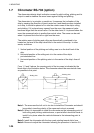
The clinometer detects ship’s inclination caused by ship’s rolling, pitching and its
output is used to stabilize the sonar beam against rolling and pitching.
The clinometer is, in principle, a pendulum. It measures the inclination of the
ship by sensing the direction of gravity acted on it and therefore when installed
on a ship, it should be placed on or near the rotation axes of the ship’s rolling
and pitching. If it is placed away upward from the axes, the measured value
becomes larger than the actual value. On the other hand, if it is placed below the
axes, the measured value is smaller than actual value. The same can be said
when it is placed far to the left or right from the axes.
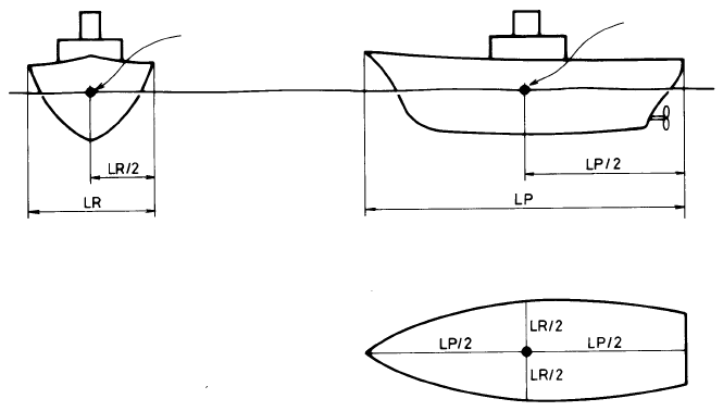
The rotation axes of pitching and rolling are theoretically considered to be
located on the level of the ship’s draft and in the center of the ship. In other
words, as follows:
1. Vertical position of the pitching and rolling axes is on the draft level of the
ship.
2. Horizontal position of the rolling axis is in the center of the ship’s
port-starboard line.
3. Horizontal position of the pitching axis is in the center of the ship’s fore-aft
line.
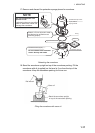
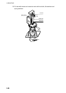
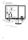
From 1, 2 and 3 above, the crossing point of the two axes is indicated by the
black dots in the illustration below. The clinometer should be mounted as close
as possible to this point.
Rolling Axis
Pitching Axis
Water line
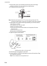
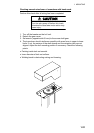
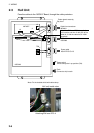
Note 1: The area near the hull unit is too low to install the Clinometer and should
be avoided, since the polarity of the measured value is reversed.
Note 2: When it is impossible to install the clinometer on the intersecting point of
both rolling and pitching rotational axes, a special effort should be made to
install it at a place where the vertical distance to the intersecting point is
shortest.
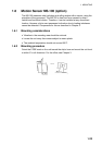
Note 3: Install the clinometer with the bow mark pointing toward ship’s bow.
Note 4: Be sure to adjust the clinometer following the procedure in section 3.6.