


2-1
2. WIRING
2.1 Wiring Among Units
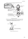
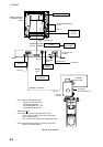
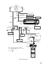
• The figure on the next page shows wiring among units.
• The signal cables are fitted with connectors. Connect the cables to the monitor,
transceiver and hull units referring to the interconnection diagram on page
S-1.
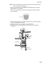
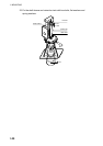
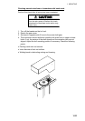
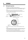
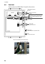
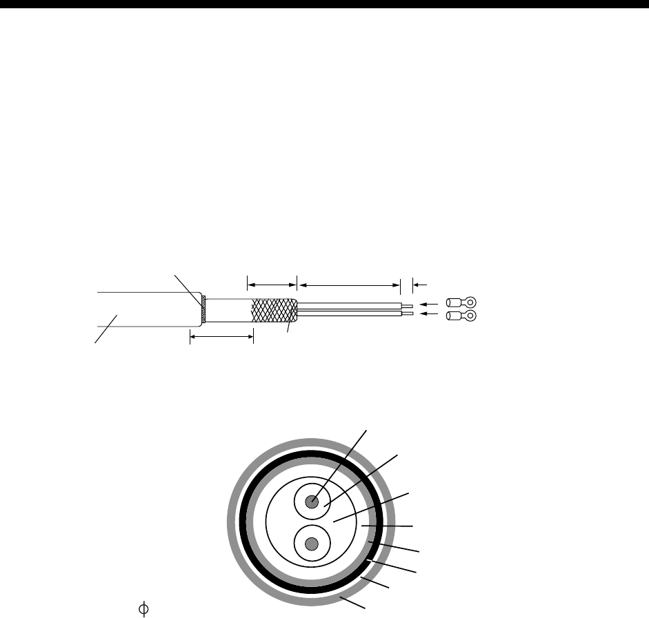
• The power cable should be arranged locally. Use power cable type
DPYCYS-2.5 (Japan Industrial Standard cable) or equivalent cables. Attach
crimp on lugs (FV2-4) as shown below.
30
5
40
Vinyl sheath
Braided shield
(Fold the braided shield back on the vinyl sheath.
Fix here with the cable clamp.)
FV2-4 (blue)
Wind
vinyl tape.
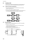
Armor
Conductor
Insulator
Inclusion
Tape
Braided shield
Sheath
Armor
Vinyl sheath
S = 2.5 mm
=15.2 mm
2
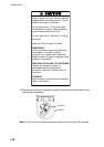
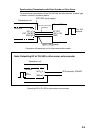
• The raise/lower drive motor and breaker are different depending on ship’s
mains.
• Install the mains switch for the sonar where it can be easily accessed. Turn off
this switch when the sonar is not being used, to reduce power consumption
and to prevent the transducer from slipping by vibration.
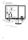
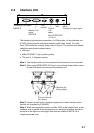
• If the D-sub connector is too large to pass through the hole in a bulkhead, etc.
remove it, pass the cable through the hole and then reattach the connector.