


1-16
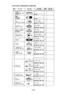
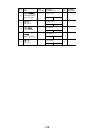
External E/S interface installation kit
traPyt'Q,epyT.oNedoCyt'Q
.yssAecafretnIS/ElanretxE--1
.yssArotcennoCHX)P6-6(213-60038-055-6001
wercS6x3M301-188-0004
wercS8x3M404-188-0001
seiTelbaC942.oN178-515-0001
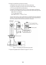
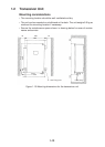
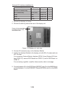
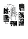
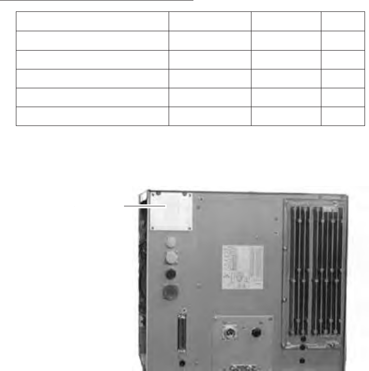
1. Remove the display unit cover.
2. Remove the dummy plate at the rear of the display unit.
Remove this dummy plate
and fasten External Inter-
face module here.
Figure 1-19 Display unit, rear view
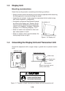
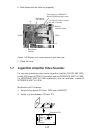
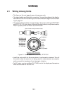
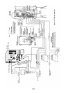
3. Connect XH connector assy. to the Interface Module.
4. Fasten the Interface Module to the display unit with M3 x 6 screws and one
M3 x 8 screw.
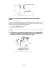
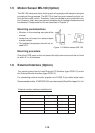
For connecting External Monitor Interface (OP06-14) and External E/S inter-
face (OP06-13), remove ESIF Board from OP06-13, and fix ESIF Board on
OP06-14.
For connecting logarithm amplifier video sounder, refer to next page.
5. Connect between J2 on the ESIF Board (06P0237) and J3 on the MAIN Board;
connect between J1 on the RGB-BUFF Board (03P9229) and J4 on the MAIN
Board.