


1-17
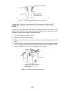
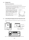
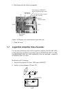
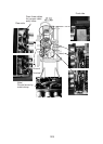
6. Bind cables with the cable tie (supplied).
External
Interface module
J3
J4
Bind cables
with cable tie.
MAIN Board
06P0227
Pass cables from RBG-BUFF
Board (03P9229) through clamp.
FRONT REAR
Fix External Interface module
with M4 x 8 screws.
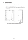
Figure 1-20 Display unit, cover removed, right side view
7. Close the cover.
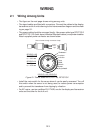
1.7 Logarithm Amplifier Video Sounder
For connecting external video souder (logarithm amplifier:FCV-291,292,1000),
modify ESIF board of OP06-13 (as below) and the INTERFACE UNIT VI-1100A.
For INTERFACE UNIT VI-1100A modification, refer to installation manual of
INTERFACE UNIT VI-1100A.
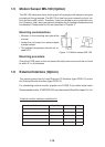
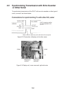
Modification of E/S interface
1. Remove chip resistor R14 from ESIF board (06P0237).
2. Solder vinyl wire between TP2 and TP4.
06P0237
R14
TP4
TP2
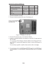
06P0237
TP3
R14 TP2
TP1
TP0
TP4
J1
Remove R14
Vinyl wire