


3-2
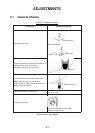
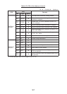
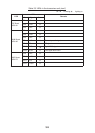
Table 3-1 General checks (con’t)
metIkcehCgnitaR,tniopkcehC
kcehcgniriW
.detcennocyltcerroceraselbacllA•
tcatnochtiwdexifylthgiteraseriwdaelllA•
.sgulno-pmircrosnip
.denetsafylmriferaswercsllA•
.derucesylmriferaselbaC•
.dednuorgylreporperasdleihselbaC•
ecnerefretnidnaesionfoecruosgnitcejeR
-oidar,rotom(yrenihcamgnitarenegesioN•
decalptonera).cte,tesVT,enohpelet
.ybraen
ehtnidecalptonerasecivedcitengaM•
.tinuyalpsidfoytiniciv
dnuorG .partsreppocahtiwdednuorgsitinuhcaE
egatlovsniams'pihS .CDV23ro42elbatssiegatlovsniams'pihS
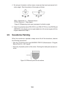
ssenthgitretaW
ydobniamehtmorfkaeltondluohsretaW
.tfahsniamehtgnolaroegnalf
tnemngilagnidaeH .gniraebtcerrocehtnodeyalpsidsitegratA
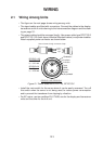
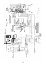
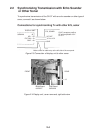
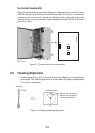
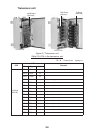
3.2 Adjustment of Transceiver Unit
Selecting audio frequency
Select audio frequency of 1000 Hz or 900 Hz by jumper connector JP2 on pcb
06P0192 in the transceiver unit. The default setting is 1000 Hz. Refer to Figure
3-1 for the location of JP2.
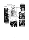
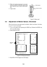
Signal offset adjustment
When noise appears on the screen, adjust R61 (offset) on pcb 06P0192. Turning
R61 clockwise slices off low level signals in a similar way to the CLUTTER con-
trol on the display unit. (While the CLUTTER control on the display unit elimi-
nates low level signals without changing signal level of strong signals, R61 shifts
signal level of all signals.) When the offset adjustment is necessary, set R61 fully
counterclockwise. Refer to Figure 3-1 for the location of R61.