


2-1
WIRING
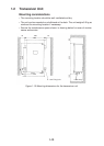
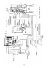
2.1 Wiring Among Units
• The figure on the next page shows wiring among units.
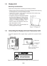
• The signal cables are fitted with connectors. Connect the cables to the display,
transceiver and hull units referring to the interconnection diagram and the draw-
ing on page S-1.
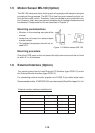
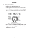
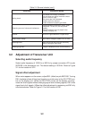
• The power cable should be arranged locally. Use power cable type DPYCYS-2
and DPYCYS-1.25 (both Japan Industrial Standard cables) or equivalent cables.
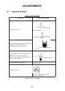
Attach supplied power connector as shown below.
Conductor*
DPYCYS-1.25
S = 1.25 mm
2
φ = 14.1 mm
DPYCYS-2.0
S = 2.0 mm
2
φ = 15.2 mm
Vinyl sheath
Armor
Tape
Insulator
Inclusion
Sheath
DPYCYS-1.25, DPYCYS-2
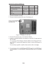
#1 pin (+)
#3 pin
#2 pin (-)
Ground armor through connector clamp.
Braid
Figure 2-1 Power cable DPYCYS-1.25, DPYCYS-2
• Install the main switch for the sonar where it can be easily accessed. Turn off
this switch when the sonar is not being used, to reduce power consumption
and to prevent the transducer from slipping by vibration.
• For AC mains, use two rectifiers RU-1746B, one for the display and transceiver
units and the other for the hull unit.