


iii
TABLE OF CONTENTS
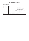
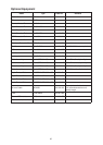
EQUIPMENT LISTS ................................................................................................... iv
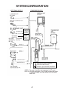
SYSTEM CONFIGURATION ................................................................................... v
MOUNTING
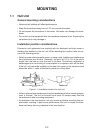
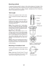
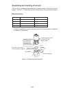
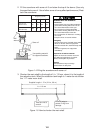
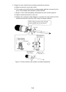
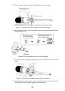
1.1 Hull Unit ..................................................................................................................... 1-1
1.2 Transceiver Unit ...................................................................................................... 1-13
1.3 Display Unit ............................................................................................................. 1-14
1.4 Grounding the Display Unit and Transceiver Unit ................................................... 1-14
1.5 Motion Sensor MS-100 (Option) ............................................................................. 1-15
1.6 External Interface (Option) ...................................................................................... 1-15
1.7 Logarithm Amplifier Video Sounder ........................................................................ 1-17
1.8 Clinometer BS-704 (option)..................................................................................... 1-19
WIRING
2.1 Wiring Among Units................................................................................................... 2-1
2.2 Synchronizing Transmission with Echo Sounder or Other Sonar ............................. 2-4
ADJUSTMENTS
3.1 General Checks ........................................................................................................ 3-1
3.2 Adjustment of Transceiver Unit ................................................................................. 3-2
3.3 Heading Alignment .................................................................................................... 3-3
3.4 Adjustment of Motion Sensor, Clinometer................................................................. 3-4
3.5 Soundome Painting ................................................................................................... 3-5
3.6 LED Status ................................................................................................................ 3-6
CHANGING SPECIFICATIONS
4.1 System Menu ............................................................................................................ 4-1
INSTALLATION MATERIALS, SPARE PARTS, ACCESSORIES .... A-1
OUTLINE DRAWINGS ............................................................................................ D-1
INTERCONNECTION DIAGRAM ...................................................................... S-1