


2-5
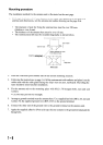
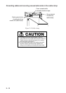
20. Route the signal cable beneath the lower left side of the terminal board fixing plate for the
RTB-801. Shorten conductors of the signal cable considering their locations on the RTB-
801.
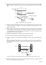
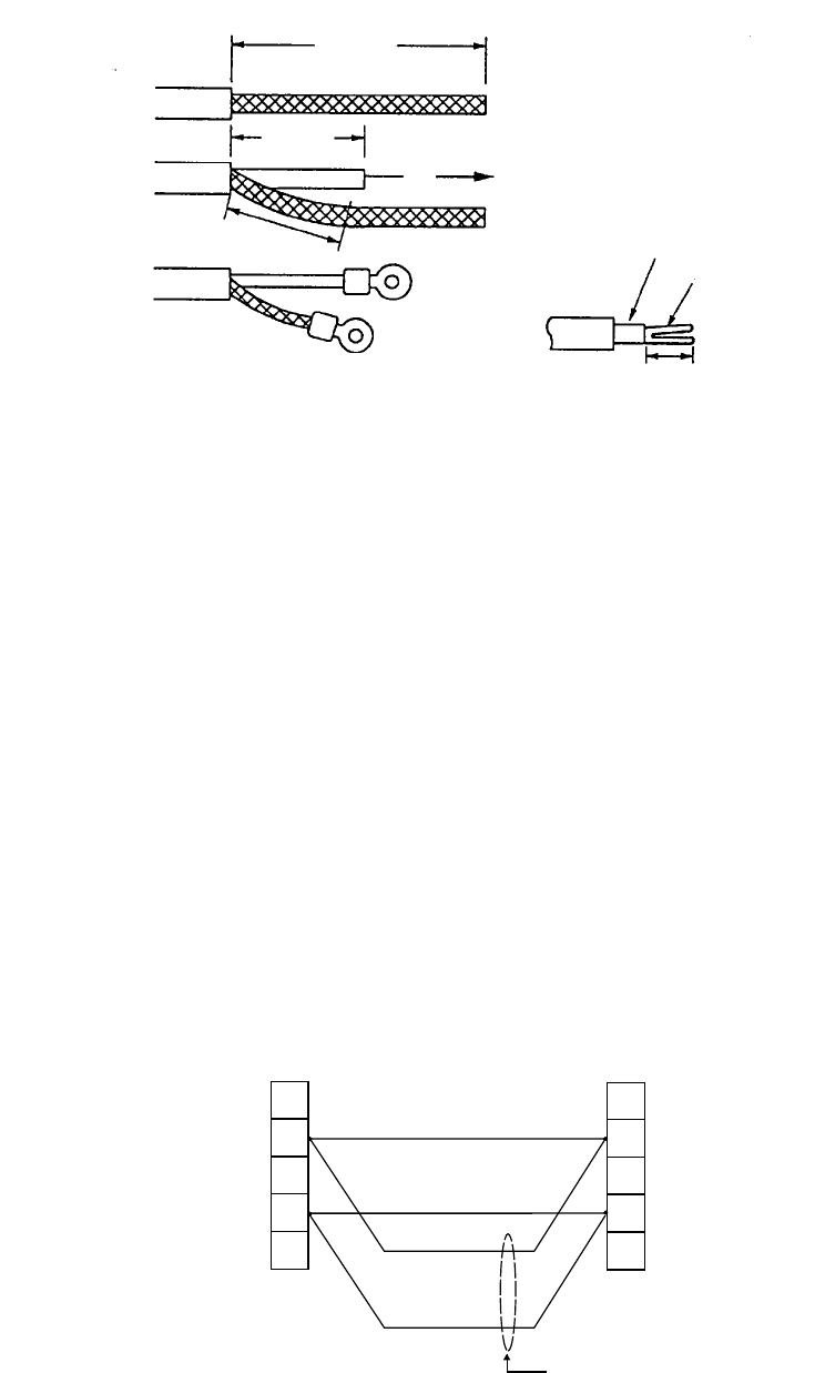
Coaxial cable
2C-2V
50 mm
45 mm
Fold back the conductor
as illustrated below.
75 mm
Inner core
Conductor
6 mm
Crimp-on lug
FVD1.25-3
(Red, ∅3)
Crimp-on lug
FV1.25-M3
(Red, ∅3)
Figure 2-9 Fabrication of coaxial cable
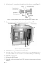
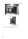
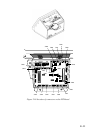
21. Shorten the shield considering the distance to the ground terminal on the left side of the
scanner unit chassis. (See Figure 2-7 for location.) Attach the crimp-on-lug FV5.5-4 (ø4,
yellow) to the shield.
22. Remove approx. 6 mm of the vinyl insulation from the end of each conductor and fix the
crimp-on lug FV1.25-M3 (Red) to each conductor. As shown in Figure 2-8, fold back the
coaxial cable four times and attach the crimp-on-lug FVD1.25-3 (ø3, red). Attach the crimp-
on-lug FVD1.25 (ø3, red) to the shield.
23. Tighten the clamping gland, and then seal the cable gland with putty.
24. Fasten the shield to the ground terminal on the scanner unit chassis.
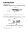
25. Connect conductors to the terminal board RTB-801 referring to the interconnection dia-
gram.
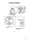
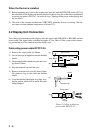
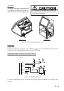
When the length of the signal cable is more than 150 m, remove the solder at terminal Nos.
24 (red) and 26 (black) on the DJ-1 connector. (#24 and #25 are spares.). Fasten the wires as
shown below.
14
16
14
16
YELLOW, LARGE
WHITE, LARGE
RED, LARGE
BLACK, LARGE
DJ-1
TB801
HEATER HOT
+12V
SCANNER
UNIT
DISPLAY
UNIT
Length 150 m
or more
Figure 2-10 Wiring on terminal boards when length of signal cable is 150 m or more
26. Check for miswiring, loose screws. Grease the fixing bolts for the cover, gasket, and tap
holes in the scanner chassis. Attach the cover.