


2-9
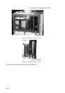
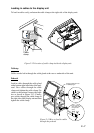
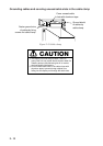
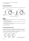
Grounding
The display unit must be grounded from
a grounding stud having a wing nut lo-
cated at the point shown in Figure 2-16.
Figure 2-16 Grounding the display unit
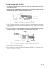
Radar buoy
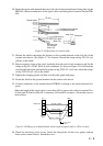
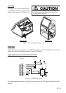
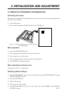
Solder the radar buoy signal line to the "BUOY" connector on the VDA Board. Connect the
trigger line to the corresponding connector on the INT Board.
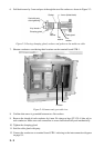
Signal input/output circuit (INT Board INT-9170)
1 TXD1-H
J450
+5V
+5V+5V
+5V
Vcc
A
1
2
5
6
4
X
OUT
GND
2 TXD1-C
3 RXD1-H
4 RXD1-C
5 DTR1-H
6 DTR1-C
7 DSR1-H
8 DSR1-C
PC900V
2SC1015
+5V
Nav data
+5V
Figure 2-17 INT Board circuit
For other input/output circuits, see the circuit diagram of the INT Board at the back of this
manual.
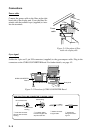
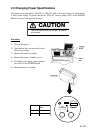
Tabletop type Pedestal type
CAUTION
An ungrounded unit can cause electrical shock when
its metallic parts are touched and give off or receive
electromagnetic interference.