


2 - 8
Connections
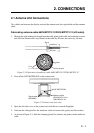
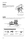
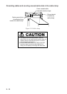
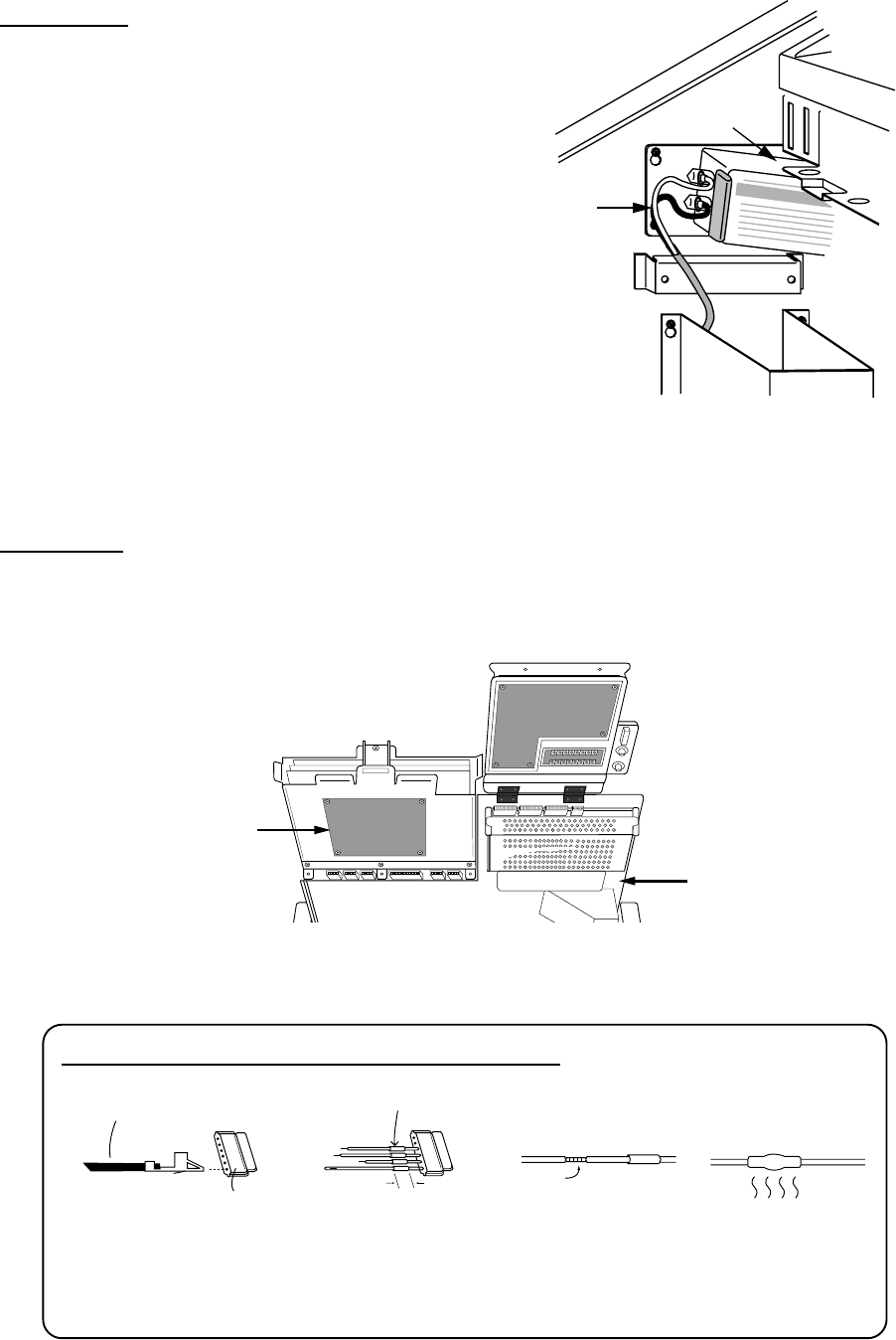
Power cable
Connect the power cable to the filter at the right
hand side of the display unit. Cover the filter ter-
minals with the terminal caps (supplied) to insu-
late the terminals.
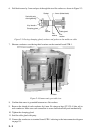
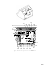
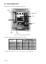
Gyro signal
Solder the 5 pin and 3 pin VH connectors (supplied) to the gyrocompass cable. Plug in the
connectors on the GYRO CONVERTER Board. For further details, see page 4-2.
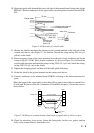
Figure 2-15 Location of GYRO CONVERTER Board
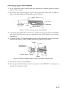
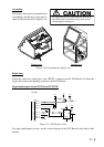
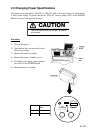
20mm
1 Insert NH connector
wire into NH connector
housing.
2 Cut shrink tubing
in 20 mm lengths and
slip onto each wire.
3 Solder connector
to signal cable.
4 Heat shrink
tubing with solder-
ing iron.
NH connector wire
Shrink tubing
NH connector
housing
Solder
HOW TO ATTACH NH CONNECTOR TO SIGNAL CABLE
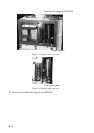
Figure 2-14 Location of filter
inside the display unit
GYRO CONVERTER
Board
Rear panel
Power
cable
Filter