


Service
24 309497L
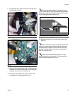
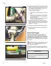
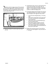
13. Assemble the covers (18 & 19). Insert several of the
screws (12) to temporarily hold the cover halves (18
& 19) together. Test the display by inserting a bat-
tery (11) and powering on the unit.
If the display does not appear:
• make sure that a charged battery (11) is being
used.
• check that the connections from the new bezel
(31) to the circuit board (112) are fastened cor-
rectly and securely.
• check that all remaining parts are repositioned
securely and in the correct location.
14. If the display appears and is operating correctly,
replace the remaining screws (12) and (42) that fas-
ten the cover halves (18 & 19) together. Torque all
screws to 7 - 10 in. lbs.
15. Replace the rear boot (24) and impact guard (40).
16. Attach the meter to the fluid line by following steps
listed on page 9.
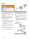
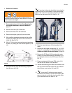
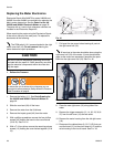
Replacing the Trigger
Trigger Repair Kits 246439 for meter 246008 and
249883 for meter 249881 are available and can be
ordered separately. See the Parts List for the 246008
and 249881 Electronic Meters on page 33. The parts
with a ✓ next to their reference numbers are included in
this repair kit.
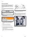
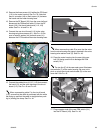
The PSM switch (101) comes attached to the right
meter cover half (18). Do not remove it during the
meter cover repair procedure.
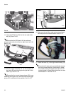
When repairing the meter using the Trigger Repair Kit,
use all of the new parts. To replace the parts do the fol-
lowing.
F
IG. 29
F
IG. 30
F
IG. 31
CAUTION
Be sure to use the disposable grounding wrist strap
included with the repair kit. Static electricity can dam-
age the electrical components within the meter as the
repair is completed.