


Service
30 309497L
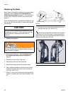
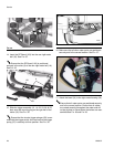
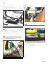
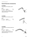
18. Insert the RF Board (103) into the meter cover (18).
Make sure that the RF board (103) fits securely into
the two slots (A). See F
IG. 46.
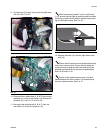
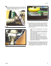
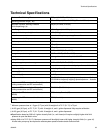
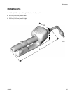
Ensure that all meter parts are positioned securely
and in the correct location. Ensure that all cables are
routed correctly throughout the meter and will not be
pinched or kinked when the halves are reassembled
See F
IG. 47 and FIG. 48.
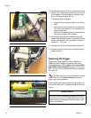
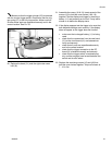
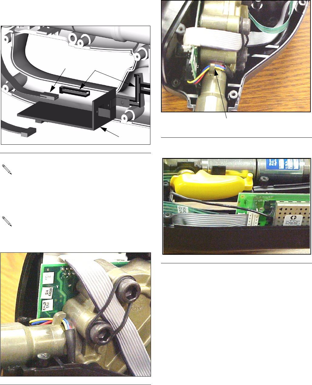
Ensure that the black antenna wire is not posi-
tioned between the ribbon cables. Pull antenna away
from the cable as shown. See F
IG. 49.
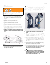
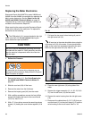
19. Slide the trigger assembly (13, 14, 22, 23, 35, & 36)
onto the mounting peg on the right side of the new
meter half (18). See
FIG. 36.
F
IG. 46
F
IG. 47
103
101
A
FIG. 48
F
IG. 49
G