


Service
309497L 29
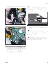
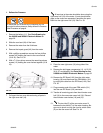
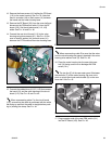
12. Remove the three screws (41) holding the PC Board
(112) to the meter housing. See F
IG. 43. Note that
there is a washer (44) on each screw (41) between
the board and the meter housing boss.
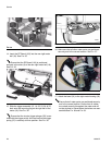
13. Remove the RF Board (103) from the cover half and
disconnect the PSM switch cable (H) from the RF
board (103). Set the old electronics (112, 103)
aside. See F
IG. 44 and FIG. 46.
14. Connect the new circuit board (112) to the valve
housing using three screws (41). See F
IG. 43. Be
sure to install a washer (44) on each screw (41)
between the PC Board and the meter housing boss.
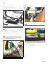
15. Connect the cables/wires (A, B, C, & D) that connect
the bezel (31) and the valve housing to the circuit
board (112). See F
IG. 43 and FIG. 44.
When reconnecting cable C to the circuit board
(112), ensure that the cable is positioned with the white
tab facing up and that the cable is straight before push-
ing in (closing) the clasp. See F
IG. 44.
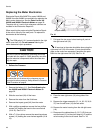
When reconnecting cable D be sure that the wires
from the valve housing are properly inserted in the valve
housing wire retainer hook (G). See F
IG. 48.
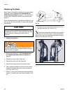
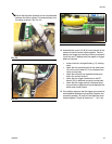
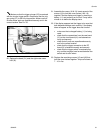
16. Place the meter housing into the new right cover
half (18) being careful not to dislodge the PSM
switch (101).
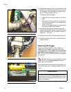
The two ribs (E) of the new meter cover fit between
the two bolts (F) of the meter housing. Be sure not to
pinch or crimp the circular switch cable (D) on the new
cover half. See F
IG. 45.
17. Plug connector end of the new PSM switch (101)
into the RF Board (103). See F
IG. 46.
F
IG. 43
C
B
41
41
41
A
D
FIG. 44
F
IG. 45
F
F
E
E
D