


Views
The following views will be added to the View Rotation when a GPS
Receiver is connected to the Matrix Fishing System:
Navigation views:
• Bird’s Eye View
• Track View
• Combo View
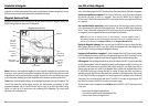
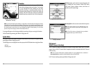
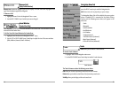
Bird’s Eye View
Bird's Eye View - This view shows a 3-D, perspective view of the track from a point above and behind
the boat (the eye point). As the boat turns, the eye point moves to follow the boat.
When you press the 4-WAY Cursor key in the Bird’s Eye View, the position of the eye point will shift.
This allows you to move and turn the eye point so that you can look off to the sides, or even behind
the boat. Pressing the RIGHT or LEFT arrow keys on the 4-WAY Cursor key turns the eye point right or
left, while pressing the UP arrow key moves the eye point forward, and pressing the DOWN arrow
key moves the eye point backward.
Pressing the EXIT key moves the eye point back to its original position behind and above the boat.
Bird’s Eye View
Depth
Boat Icon
Water Surface
Temperature
Latitude and
Longitude
Position of Boat
Speed of Boat
Bearing of Boat
with Respect
to North
Sonar
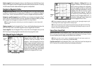
Views
Track
View
Combo
View
Bird's
Eye
View
7
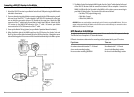
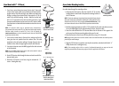
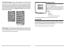
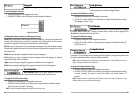
No Access Under Mounting Location
Follow these steps to deck mount the GPS Receiver in a situation where
you must route the cable to the side because there is no space for a cable
underneath the mounting location.
1. Determine the best location, then test route the 20’ (6 m) cable
from the Matrix control head to the planned mounting location of
the GPS Receiver.
NOTE: 10’ extension cables may be purchased from Humminbird if your
planned cable route exceeds 20’ (6 m). Maximum cable length, including
extension cables, should not exceed 50’ (16 m). Visit our website at
www.humminbird.com, or call our Customer Resource Center at 1-334-687-0503
to purchase extension cables.
2. Confirm that the cable length is adequate and route the cable
from the Receiver to the Matrix control head. If holes are required
to route the cable, they must be
³₄
” (19 mm) to allow for the cable
connector. Secure the NMEA pigtail with electrical tape.
3. The GPS Receiver has two wire routing notches. Use the cable
notch closest to the intended cable route.
4. With the cable routed, position the GPS Receiver in the planned
mounting location and mark the mounting holes with a pencil
or awl.
5. Move the GPS Receiver to the side and drill the two
⁵₃₂
” (4 mm)
pilot holes.
NOTE: Apply marine-grade sillicone caulk or sealant to both screw and drilled holes as needed to protect
your boat from water damage.
6. Align the screw holes of the GPS Receiver over the pilot screw holes, referring to the
illustration, and attach with the #6 -
³₄
” Phillips head screws. Hand tighten only.
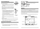
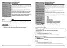
Finish Routing the Cable and Check Operation
Follow these steps to finish routing the GPS Receiver cable between the Matrix control head and
the Receiver:
1. Secure the cable along its path to the Matrix control head as needed, using cable ties.
2. Plug the GPS Receiver cable to the Matrix control head per the instructions detailed in
Connecting a GR4 GPS Receiver to the Matrix..
6
No Access Under
Mounting Location
NMEA
Pigtail
Taped
NMEA
Pigtail
Cable Out
NMEA Pigtail Taped
to Cable