INSTALLATION
CONTROL HEAD INSTALLATION
and one amp fuse (not included) for the protection of the unit (Figure 21).
Humminbird is not responsible for over voltage or over current failures.
In order to minimize the potential for interference with other
marine electronics a separate power source (such as a
second battery) may be necessary.
Step Three - Drill the Mounting Holes
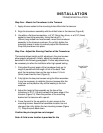
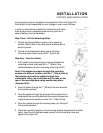
1. Set the mounting bracket in place on the mounting
surface. Mark the four mounting screw locations with a
pencil or punch.
2. Set the mounting bracket aside, and drill the four
mounting screw holes using a 9/64” (3.6mm) bit.
Step Four - Run the Cables
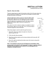
1. If the cables must pass through a hole underneath the
mounting surface, mark and drill a 1” (25mm) hole
centered between the four mounting holes (Figure 22).
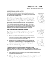
Note: if the cables must pass through the mounting
surface at a different location, drill the 1" (25mm) hole at
that location and pass the cables through from
underneath. Also, you must break out the tabs on the
rear of the mounting base using needle nose pliers
(Figures 24-25).
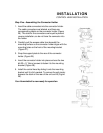
2. Insert all cables through the 1” (25mm) hole from beneath
the mounting surface.
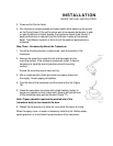
3. Pass the cables through the grommet (if the cable hole is
underneath the mounting bracket) then press the grommet
in place around the cables and into the 1” (25mm) hole.
4. Pass the cables through the mounting base, out the top of
the mounting bracket.
5. Place the mounting bracket on the mounting surface aligned with the drilled
holes. Insert the four flathead wood screws into the mounting holes and
tighten fully (Figure 23).


