


iv
FOREWORD …………………………………………………………… i
IMPORTANT …………………………………………………………… i
EXPLICIT DEFINITIONS ……………………………………………… i
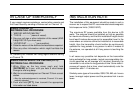
IN CASE OF EMERGENCY…………………………………………… ii
INSTALLATION NOTE ………………………………………………… ii
DOC …………………………………………………………………… iii
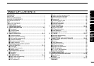
TABLE OF CONTENTS ……………………………………………… iv
PRECAUTIONS ………………………………………………………… v
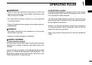
1 OPERATING RULES ……………………………………………… 1
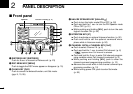
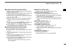
2 PANEL DESCRIPTION ………………………………………… 2–5
■ Front panel ……………………………………………………… 2
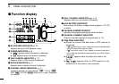
■ Function display ………………………………………………… 4
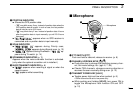
■ Microphone ……………………………………………………… 5
3 BASIC OPERATION…………………………………………… 6–11
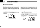
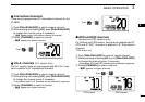
■ Channel selection ……………………………………………… 6
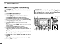
■ Receiving and transmitting……………………………………… 8
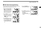
■ Call channel programming ……………………………………… 9
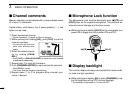
■ Channel comments …………………………………………… 10
■ Microphone Lock function …………………………………… 10
■ Display backlight ……………………………………………… 10
■ Optional voice scrambler operation ………………………… 11
4 SCAN OPERATION ………………………………………… 12–13
■ Scan types ……………………………………………………… 12
■ Setting TAG channels ………………………………………… 13
■ Starting a scan ………………………………………………… 13
5 DUALWATCH/TRI-WATCH ……………………………………… 14
■ Description ……………………………………………………… 14
■ Operation ……………………………………………………… 14
6 DSC OPERATION …………………………………………… 15–49
■ MMSI code programming……………………………………… 15
■ MMSI code check ……………………………………………… 16
■ DSC address ID………………………………………………… 17
■ Position and time programming ……………………………… 21
■ Position and time indication…………………………………… 22
■ GPS information indication …………………………………… 22
■ Distress call …………………………………………………… 23
■ Transmitting DSC calls ………………………………………… 26
■ Receiving DSC calls …………………………………………… 41
■ Received messages …………………………………………… 45
■ DSC Set mode ………………………………………………… 47
7 OTHER FUNCTIONS………………………………………… 50–54
■ Intercom operation …………………………………………… 50
■ RX Speaker function…………………………………………… 51
■ Hailer operation ………………………………………………… 52
■ Automatic foghorn function …………………………………… 53
8 SET MODE …………………………………………………… 55–57
■ Set mode programming ……………………………………… 55
■ Set mode items ………………………………………………… 55
9 CONNECTIONS AND MAINTENANCE …………………… 58–64
■ Connections …………………………………………………… 58
■ Antenna ………………………………………………………… 59
■ Fuse replacement ……………………………………………… 59
■ Supplied accessories ………………………………………… 59
■ Microphone hanger …………………………………………… 59
■ Mounting the transceiver ……………………………………… 60
■ MB-75 installation ……………………………………………… 61
■ UT-112/UT-98 installation……………………………………… 62
■ HM-162E installation…………………………………………… 63
10 TROUBLESHOOTING …………………………………………… 66
11 SPECIFICATIONS AND OPTIONS ……………………… 67–68
■ Specifications…………………………………………………… 67
■ Options ………………………………………………………… 68
12 CHANNEL LIST ……………………………………………… 69–70
TEMPLATE
TABLE OF CONTENTS
1
2
3
4
5
6
7
8
9
10
11
12