


59
9
CONNECTIONS AND MAINTENANCE
9
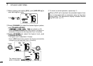
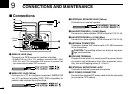
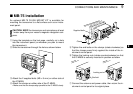
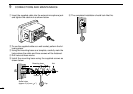
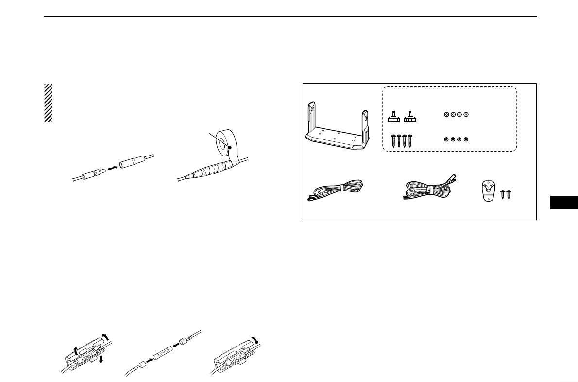
CAUTION: After connecting the DC power cable, NMEA
IN/OUT leads, external speaker lead and hailer/foghorn lead,
cover the connector and leads with an adhesive tape as
shown below, to prevent water seeping into the transceiver.
■ Antenna
A key element in the performance of any communication sys-
tem is the antenna. Ask your dealer about antennas and the
best place to mount them.
■ Fuse replacement
One fuse is installed in the supplied DC power cable. If a fuse
blows or the transceiver stops functioning, track down the
source of the problem if possible, and replace the damaged
fuse with a new one of the proper rating.
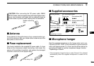
■ Supplied accessories
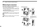
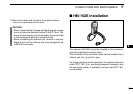
■ Microphone hanger
Rest the supplied microphone on the hanger when not in use.
Connect the OPC-1096* to the transceiver’s ground terminal
with a self-tapping screw (3 × 8 mm) and the other side to the
microphone hanger to use the microphone hanger function.
*Depending on version.
• If the microphone hanger function is used, Channel 16 is selected
automatically when the supplied microphone is rested on the
hanger.
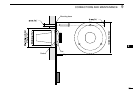
Mounting bracket For mounting bracket
DC power cable
(OPC-891A)
Microphone hanger cable*
(OPC-1096: Black)
Microphone hanger
and screws (3×16)
Knob bolts
Screws (5×20)
Flat washers (M5)
Spring washers (M5)
*Depending on version
Fuse rating: 10 A
Rubber vulcanizing
tape