


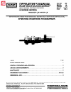


OPERATORS MANUAL
M
40
This Parts List and Service Instruction Manual is composed
48
of four sections:
A complete Parts List will be found on the various drawings
contained in this Manual.
GENERAL DESCRIPTION AND OPERATION
This Manual is provided to serve as an aid in obtaining the
AIR AND LUBE REQUIREMENTS
maximum service from this tool.
MAINTENANCE
After carefully reading this manual, file for future
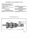
DISASSEMBLY AND REASSEMBLY OF TOOL
reference.
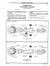
GENERAL DESCRIPTION AND OPERATION
The ARO Models 8274-(
)A and 8276-(
)A Power Motors
feature “2200” series motors with “44” series gearing.
Models 8274-(
)A are reversible rotation models with a
balanced cylinder which produces the same power in either
forward or reverse rotation. Models 8276-(
)A are single
direction models.
AIR AND LUBE REQUIREMENTS
AIR PRESSURE of 90 pounds per square inch at the air
inlet of the tool is required for maximum motor efficiency.
If necessary, an air regulator should be installed to maintain
this pressure when tool is in operation.
FILTERED AND OILED AIR will allow the tool to
operate more efficiently and yield a longer life to operating
parts and mechanisms. A line filter capable of filtering
particles larger than 50 microns should be used with a line
oiler.
CAUTION: An excessive amount of lubricant in a tool will
affect the speed and power, “2200” gearing should contain
approx. l/4 ounce of grease
and “44” gearing
should
contain approx. l/2 ounce of grease (per set of plane-
tary gearing).
RECOMMENDED HOSE SIZE - 3/8” nominal inside
diameter.
FILTER-REGULATOR-LUBRICATOR (F-R-L) assembly
Model 128231-300 is recommended for use with this Air
Tool. The capacity of the individual Filter-Lubricator is
adequate to provide clean (40 micron) oiled and regulated
air for the tool. The Filter-Regulator-Lubricator must be
installed on the stationary air line, in that order, with the
Lubricator nearest to the tool. NEVER mount the unit on
the detachable flexible hose to the tool.
RECOMMENDED LUBRICANTS: Spindle Oil (29665), 1 qt.
(.9 liter) container for oiler and air inlet; Grease 33153, 5 lb.
(2.3 kg) can for gears and bearings; “O” Ring Lubricant
36460, 4 oz. (113 g) tube for lubrication and installation of
“0” Rings: Grease 40036-1, 1 lb. (.45 kg) can for Clutch
Mechanism and Hammer parts.
FLUSH TOOL with a solution of three parts cleaning
solvent and one part light oil after each 40 hours of
operation. After flushing, apply a small amount of Spindle
Oil in air inlet and run free for one minute to insure proper
lubrication.
GEARING should be grease lubricated to a minimum of
once a month.
All models have an adjustable exhaust manifold with
muffler, flush fittings for lubrication, l/4” female n.p.t.f.
air inlet and optional air inlets at end of side of head
housing with necessary hex socket screw plugs for closure
of unused inlets.
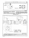
MODEL 128231-300
FILTER-REGULATOR-
GAUGE-LUBRICATOR.
MAINTENANCE
DISCONNECT AIR SUPPLY from tool or shut off air
supply and exhaust (drain) line of compressed air BEFORE
performing maintenance or service to tool.
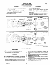
in solvent unless a good method of re-lubricating the
bearing is available. Open bearings may be washed but
should not be allowed to spin while being blown dry. When
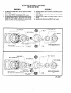
REPLACEMENT PARTS are necessary, consult drawing
AIR TOOLS are made of precision parts and should be
handled with reasonable care when servicing. Excessive
pressure exerted by a holding device may cause distortion
of a part. Apply pressure evenly when disassembling (or
assembling) parts which have a press fit. When removing or
installing bearings, apply pressure to the bearing race that
containing the part for identification.
BEFORE REASSEMBLING, lubricate parts where
required. Use 33 153 Grease, or equivalent, in bearings. Use
36460 Lubricant for “0” Ring Assembly. When assembling
“0” rings or parts adjacent “0” rings, care must be
will be the press fit to the mating part; if this is not
practiced, Brinelling of the bearing races may occur making
replacement necessary. It is important that the correct tools
and fixtures are used when servicing this Air Tool.
exercised to prevent damage to the rubber sealing surfaces.
A small amount of grease will usually hold steel balls and
other small parts in place while assembling.
DISASSEMBLY should be done on a clean work bench
with a clean cloth spread to prevent the loss of small parts.
After disassembly is completed; all parts should be
thoroughly washed in a clean solvent, blown dry with air
and inspected for wear levels, abuse and contamination.
Double sealed or shielded bearings should never be placed
WHEN ORDERING PARTS, be sure to list PART
NUMBER, PART NAME, MODEL NUMBER AND
SERIAL NUMBER OF TOOL. USE ONLY GENUINE
ARO REPLACEMENT PARTS.
FORM 286-2
-2-