


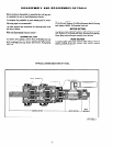


GEARING SECTION
M 40
46
GEARING SECTION
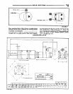
DRIVE GEARING - “44” SERIES
(36162 AND 36163)
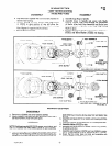
DISASSEMBLY
a. Remove Key (44285) from Spindle. Tap drive end
of Spindle with a non-metallic hammer to remove
from housing.
b. Remove Bearing (36151) and Spacer (36139).
c. Remove Shafts (36137) releasing Gears from Spindle.
d. If it should become necessary to remove Bearing
(36149) and Spacer (36153 or 36136); after removal
of Bearing (3615 1) and Spacer (36139) alternately
tap ends of Shafts (36137) to remove Bearing and
Spacer.
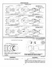
REASSEMBLY
a. Assemble Spacer (36 153 or 36 136) and Bearing (36 149)
to Spindle.
b. Assemble Gears to Spindle and secure with Shafts
(36137). Use a small screwdriver in slot of Shafts to
align Shafts to Spacer.
c. Assemble Spacer (36139) and Bearing (36151).
d. Assemble with Washer (33563) into housing.
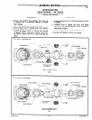
*150 - 160 FT. LB. SHEAR KEY
36136 SPACER
36135 SPINDLE
36137 SHAFT (2)
33563 WASHER
36139 SPACER
3615 BEARING
FLAT SIDE OF SPACER
36 I43 HOUSING
(10 INT. - 20 EXT. TEETH
36149 BEARING 36160 GEAR (2)
(I9 TEETH)
36162 GEARING ASS’Y:
(4:l)
*
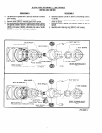
150 - 160 FT. LB. SHEAR KEY
36153 SPACER
36144 SPINDLE
36151 BEARING
FLAT SIDE OF SPACER
FLAT SIDE OF SPACER
36 : 43 HOUSING
36149 BEARING
36 I 59 GEAR (2)
(24 TEETH)
36163 GEARING ASS’Y
(7:1)
FORM 286-2
-4- FIGURE2