


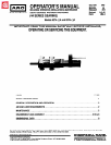


GEARING SECTION
“2200” SERIES GEARING
M 40
46
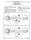
DISASSEMBLY
(41002 AND 41305)
REASSEMBLY
a. Tap drive end of Spindle with a non-metallic hammer to
a. Assemble Snap Ring to Spindle.
remove from housing.
b. Remove Bearing (33706). Rotate Snap Ring (40842
or 40843) so open portion of ring will allow the
removal of one Shaft (40481). Remove Shaft releasing
Gear. Repeat for opposite Shaft and Gear.
c. Remove Bearing (33704).
b. Assemble Gears to Spindle and secure with Shafts
(40841). Rotate Snap Ring allowing the installation
of Shafts. After both Gear assemblies and Shafts have
been assembled to Spindle, rotate Snap Ring locking
Shafts in place.
c. Assemble Bearings to Spindle and assemble with Washer
(47590) and Wave Washer (47589) into housing.
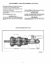
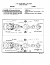
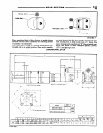
41000 HOUSING
46416 GEAR (2)
40999 SPINDLE
40843
SNAP RING
4227 1 BEARING (4)
40841 SHAFT (2)
3704 BEARING
47589 WAVE WASHER
*
NOT lNCLUDED IN GEARING ASS'Y
41000 HOUSINGS
41164 SPINDLE
40842
SNAP RING
0841 SHAFT (2)
3704 BEARING
47589 WAVE washer
34574 GEAR
(7 INT - 15 EXT TEETH)
* NOT INCLUDED IN GEARING ASS’Y
INCLUDES 33517 GREASE FITTING
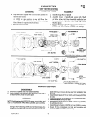
a. Remove nut (33694) and sems fastener (33700).
b. Grasp cylinder in one hand and tap drive end of rotor with a
soft face hammer; motor will come apart.
ASSEMBLY
NOTE: Pack bearings with ARO 33153 grease, or equivalent, and
coat i.d. of cylinder with ARO 29665 spindle oil upon assembly.
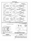
a. Assemble bearings into end plates, pressing on outer race of
bearings. NOTE: Bearing (33709) is a flush face bearing. As-
semble into end plate with flush face of bearing towards end
plate (lettering on bearing facing away from end plate). See
figure 5.
b. Assemble end plate (33710 or 34485) with bearing (33709)
to rotor.
c. Assemble cylinder to end plate (33710 or 34485) and rotor.
d. Assemble blades (41520) to rotor.
e. Assemble end plate (33712 or 34486) with bearing (33705)
to cylinder and rotor.
f. Assemble sems fastener (33700) and nut (33694) to motor.
NOTE: Torque fastener to 28 in. Ibs and nut to 9 - 12 ft Ibs.
g. Insure that the motor does not bind and assemble with
spacers (33699 and 33711) into housing.
FORM 286-2
-6-