


DISASSEMBLY AND REASSEMBLY OF TOOLS
Before starting to disassemble or reassemble this tool (any part
or completely) be sure to read Maintenance Section.
To minimize the possibility of parts damage and for conve-
nience, the steps for disassembly or reassembly listed on the
following pages are recommended.
The basic sections and instructions for removing them from
tool are as follows:
With tool disconnected from air service-
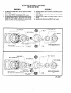
GEARING SECTION
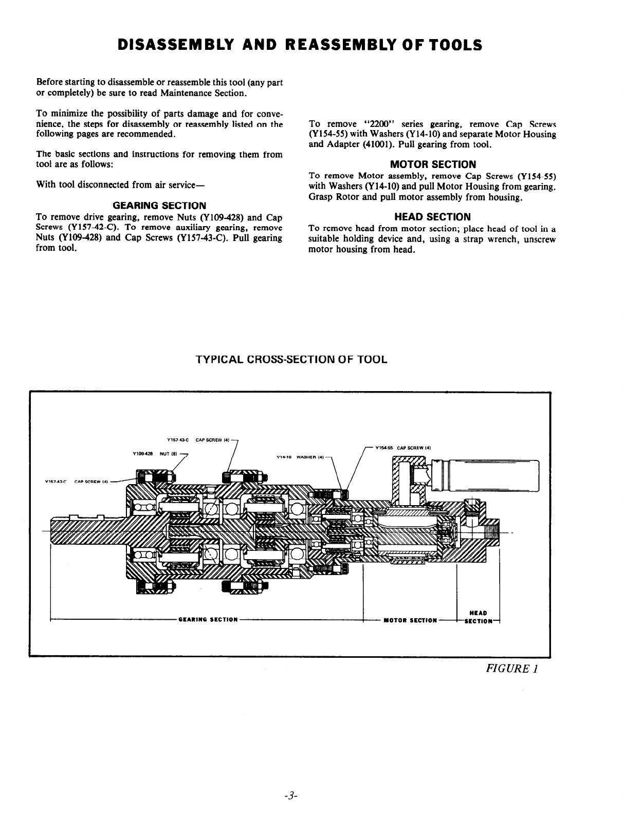
To remove drive gearing, remove Nuts (Y109-428) and Cap
Screws (Y157-42-C). To remove auxiliary gearing, remove
Nuts (Y109-428) and Cap Screws (Y157-43-C). Pull gearing
from tool.
To remove
“2200” series gearing, remove Cap Screws
(Y154-55) with Washers (Y14-10) and separate Motor Housing
and Adapter (41001). Pull gearing from tool.
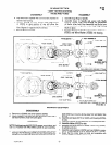
MOTOR SECTION
To remove Motor assembly, remove Cap Screws (Y154-55)
with Washers (Y 14-10) and pull Motor Housing from gearing.
Grasp Rotor and pull motor assembly from housing.
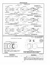
HEAD SECTION
To remove head from motor section; place head of tool in a
suitable holding device and, using a strap wrench, unscrew
motor housing from head.
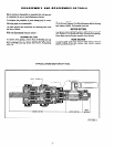
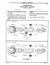
TYPICAL CROSS-SECTION OF TOOL
FIGURE 1
-3-