


Contents
Intel® Server Chassis SC5300 User Guide xvii
Figures
Figure 1. Screw Description.........................................................................................................1
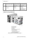
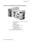
Figure 2. Intel® Server Chassis SC5300 Base Front View..........................................................2
Figure 3. Intel® Server Chassis SC5300 LX Front View .............................................................3
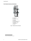
Figure 4. Pedestal Controls and Indicators..................................................................................4
Figure 5. Intel® Server Chassis SC5300 Base Chassis Rear View ............................................6
Figure 6. Intel® Server Chassis SC5300 BRP and SC5300 LX Chassis Rear View...................7
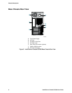
Figure 7. Intel® Server Chassis SC5300 Side View....................................................................8
Figure 8. Removing the Access Cover ......................................................................................12
Figure 9. Removing Bezel Assembly.........................................................................................13
Figure 10. Removing Air Ducts..................................................................................................14
Figure 11. Removing Hot Swap Fans........................................................................................15
Figure 13. Routing Power Cables to Fixed Drives.....................................................................17
Figure 14. Routing SCSI/SATA Data Cables.............................................................................18
Figure 15. Removing Slide/Filler Panel Assembly from Upper Device Bay...............................18
Figure 16. Installing Slides on 3.5-in Floppy Drive.....................................................................19
Figure 17. Removing Slide/Filler Panel Assembly from Upper Device Bay...............................20
Figure 18. Installing a DVD or CD-ROM Drive...........................................................................20
Figure 19. Removing Six-drive Fixed Drive Cage from Chassis................................................21
Figure 20. Unlocking and Opening Upper Drive Cage Door......................................................21
Figure 21. Opening Lower Drive Cage Door..............................................................................22
Figure 22. Remove Slides from Drive Cage Door......................................................................22
Figure 23. Installing Device Slides to Hard Drive.......................................................................23
Figure 24. Inserting Drive/Slide Assembly into Drive Cage .......................................................23
Figure 25. Closing Lower Door of Fixed Drive Cage .................................................................24
Figure 26. Closing Upper Door of Fixed Drive Cage .................................................................24
Figure 27. Tightening Thumb Screw..........................................................................................24
Figure 28. Releasing Drive Carrier from Hot Swap Cage..........................................................25
Figure 29. Removing Plastic Retention Device..........................................................................25
Figure 30. Securing Hard Drive to Drive Cage .........................................................................25
Figure 31. Inserting Drive Carrier into Drive Cage.....................................................................26
Figure 32. Installing a Hot Swap Fan.........................................................................................26
Figure 33. Removing Adhesive from Air Dam............................................................................27
Figure 34. Installing Air Dam......................................................................................................27
Figure 35. Securing Cables in Chassis with a Hot Swap Power Supply....................................28
Figure 36. Remove PCI Add-in Card Retainer...........................................................................29
Figure 37. Preparing the Chassis for a PCI Add-in Board .........................................................30
Figure 38. Installing an Add-in Board.........................................................................................31
Figure 39. Replacing PCI Add-in Card Retainer........................................................................32
Figure 40. Removing Inner Plastic Air Baffle from Processor Air Duct......................................33
Figure 41. Removing Outer Plastic Air Baffle from Processor Air Duct .....................................33
Figure 42. Installing Air Ducts....................................................................................................34
Figure 43. Removing Power Supply Filler Panel .......................................................................35
Figure 44. Installing Additional Hot Swap Power Supply Module ..............................................35
Figure 45. Installing Bezel Assembly.........................................................................................36
Figure 46. Installing the Access Cover ......................................................................................37
Figure 47. Removing a Fixed Fan..............................................................................................41
Figure 48. Removing a Hot Swap Fan.......................................................................................42