


Maintaining Your Server
44 Intel® Server Chassis SC5300 User Guide
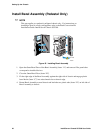
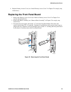
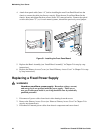
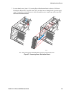
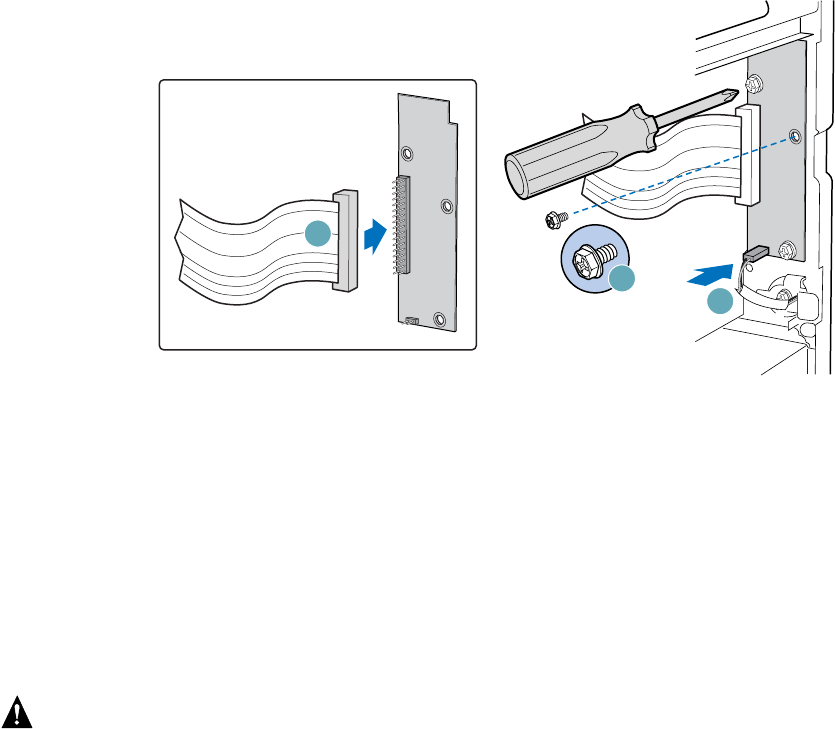
4. Attach front panel cable (letter “A”) before installing the new Front Panel Board into the
chassis to ensure the cable pins line up correctly. Place the new Front Panel Board in the
chassis. Insert and tighten the three screws (letter “B”) removed earlier. Connect the optical
switch cable (letter “C”) or, for rack-mount systems, reinstall the previously saved jumper.
TP00692
A
B
C
Figure 51. Installing the Front Panel Board
5. Replace the Bezel Assembly (see “Install Bezel Assembly” in Chapter 2 for step-by-step
instructions).
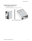
6. Replace the Primary Access Cover (see “Install Primary Access Cover” in Chapter 2 for step-
by-step instructions).
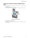
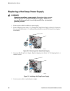
Replacing a Fixed Power Supply
WARNINGS
Hazardous conditions, power supply: Hazardous voltage, current,
and energy levels are present inside the power supply. There are no
user-serviceable parts inside it; servicing should be done by technically
qualified personnel.
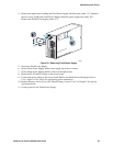
1. Disconnect all power cables from chassis after shutting down the server.
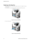
2. Remove the Primary Access Cover (see “Remove Primary Access Cover” in Chapter 2 for
step-by-step instructions).
3. Disconnect all internal power cables from chassis components and server board.