


Setting Up the Chassis
18 Intel® Server Chassis SC5300 User Guide
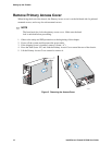
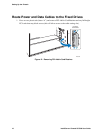
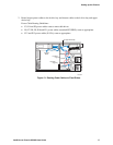
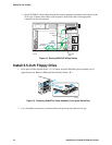
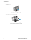
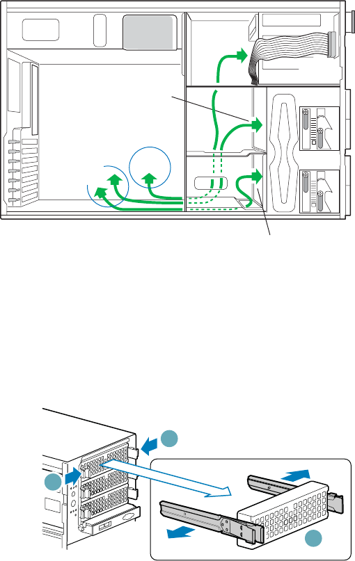
3. Route SCSI/SATA data cables through the chassis openings located near the bottom of the
drive cage. Connect data cables to the respective fixed drive and to the appropriate
connector on the server board.
TP00552
To 4-Drive
Cage
To 6-Drive
Cage
4/6-Drive
Bay Cables
Upper
Bay Cables
Figure 14. Routing SCSI/SATA Data Cables
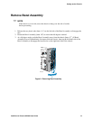
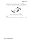
Install 3.5-inch Floppy Drive
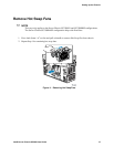
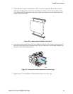
1. Press pair of slides inward (letter “A”) to release and pull slide/filler panel assembly out of
upper device bay. Remove EMI panel from bracket (letter “B”).
TP00535
A
A
B
Figure 15. Removing Slide/Filler Panel Assembly from Upper Device Bay
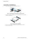
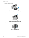
2. Use a flat blade screwdriver to remove the knock-out insert from the front of tray.