


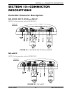
SECTION 10—CONNECTOR DESCRIPTIONS
MK
5
™NX™Electronics 38 Part No 1110532
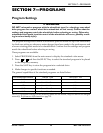
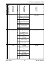
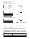
Battery Connector Pinout
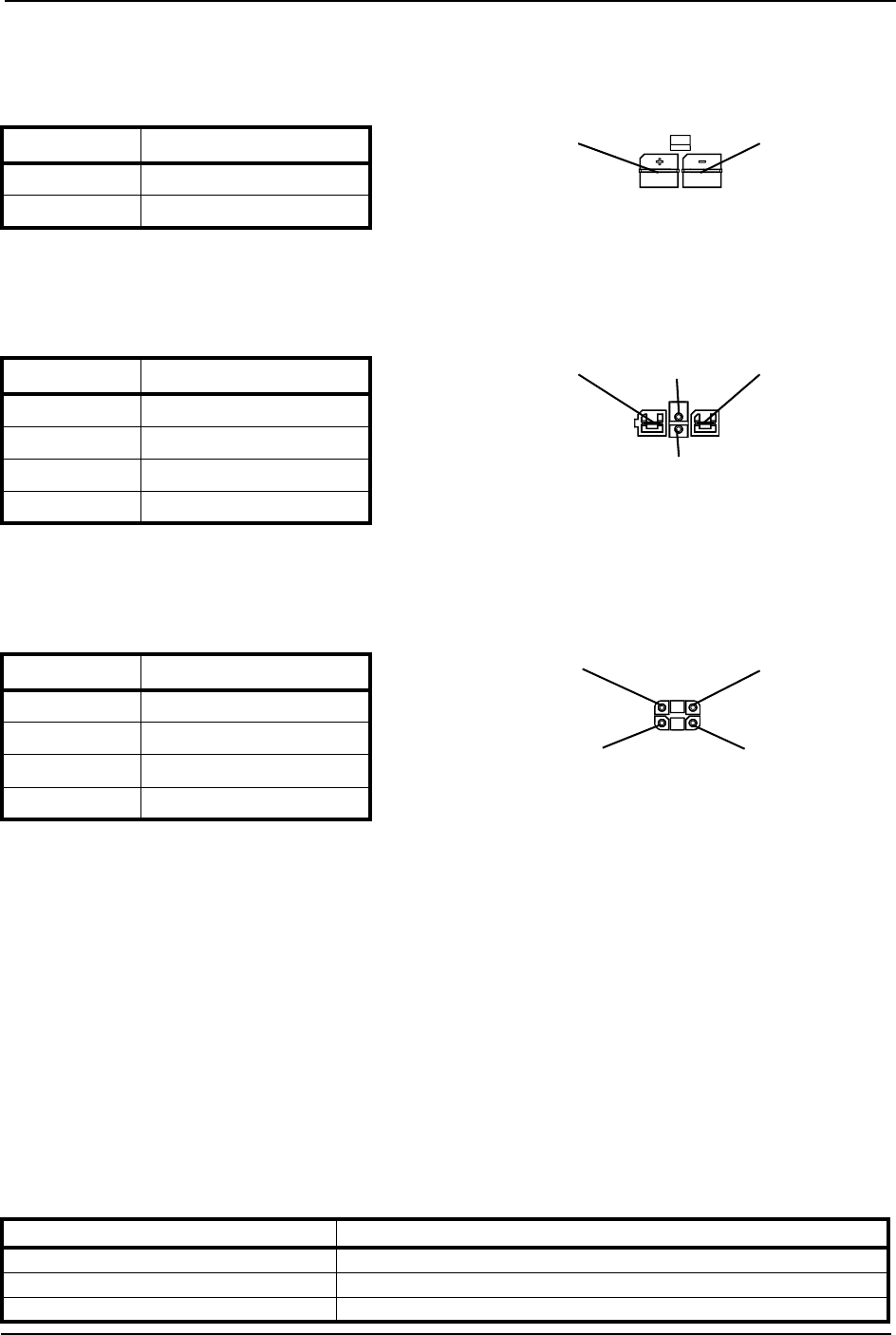
NOTE: For this procedure, refer to FIGURE 10.3.
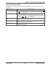
FIGURE 10.3 Battery Connector Pinout
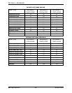
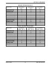
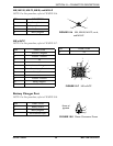
Motor Connector Pinout
NOTE: For this procedure, refer to FIGURE 10.4.
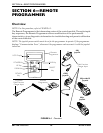
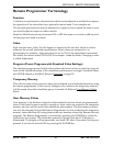
FIGURE 10.4 Motor Connector Pinout
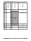
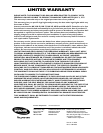
Joystick Connector Pinout
NOTE: For this procedure, refer to FIGURE 10.5.
FIGURE 10.5 Joystick Connector Pinout
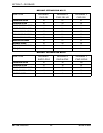
Drive Control Input (DCI)
NOTE: Wheelchairs equipped with DCI have seating options (i.e. elevate and tilt).
The DCI allows the wheelchair mode to depend on the resistance of the DCI “Loop”:
• Inhibit - prevents the wheelchair from driving, typically when the wheelchair is being
charged, or when the seat is tilted.
• Slow - limits the drive speed to a predetermined value, typically when the seat is
raised.
To determine the mode, an appropriate resistance must be placed across the DCI input
pin (I) and the DCI Battery Negative (-) pin. Depending on the resistance value, the
controller will inhibit, slow, and/or swivel driving. Resistors used must be 5% tolerance
resistors.
PIN FUNCTION
1 Battery Positive
2 Battery Negative
1
2
PIN FUNCTION
1 Motor Positive
2 Motor Negative
3 Park Brake Negative
4 Park Brake Positive
1
2
4
3
PIN FUNCTION
1 Battery Positive
2 Communication Bus High
3 Communication Bus Low
4 Battery Negative
1
2
4
3
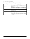
MODE RESISTANCE
Inhibit 0
Slow 120
Normal Open