


2
1 INSTALLATION
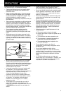
ANTENNA CONNECTION
In general, HF/ 50 MHz mobile antennas are larger and heavier than VHF/ UHF antennas. Therefore, use a
strong and rigid mount to safety and securely install the HF/ 50 MHz mobile antenna.
A bumper mount is recommended for stable mounting. However, most recent models of vehicles have plastic
bumpers. For such vehicles, ground the antenna mount to the body chassis with a large wire. Antenna
installation is critical for successful mobile operation. For further information, refer to The Radio Amateur’s
Handbook, Radio Handbook, or other published texts.
GROUND CONNECTION
The ground, which is the other half of the antenna system, is very important when using a mobile whip type
antenna. Connect the feed line ground for the antenna securely to the vehicle’s chassis, and be certain to bond
(electrically connect) the vehicle’s body to chassis. The sheet metal will provide the primary ground plane, so be
sure to establish a good RF connection from the feed line to both the chassis and the body. For comprehensive
information on mobile antennas installations and optimization, refer to the ARRL Handbook or similar publications.
IGNITION NOISE
This transceiver has been equipped with a Noise Blanker and Digital Noise Limiter to filter ignition noises out.
However, some cars may generate excessive ignition noise. If there is excessive noise, use suppressor spark
plugs (with resisters), and/ or DC line filters to reduce the electric noises. The ARRL Handbook, or similar
refereneces, has a wealth of information regarding this topic.
Note:
◆
After installation and wiring are completed, confirm that all work has been done correctly, then connect the DC power cable plug(s) to the
transceiver.
◆
If the fuse blows, disconnect the DC power cable plug(s) from the transceiver immediately, then check all the DC power cables to find the
reasons of the short circuit. The DC cable may be damaged, short circuited, pinched, or squashed. After resolving the problem, replace the
fuse with one of the same type and rating.
◆
Do not remove the fuse holder for any reason.
DC
DC
13.8V
13.8V
1
DC 2 13.8V
AT
GN
D
GND
GND
2
2
1
12 V battery
DC IN
Red (+)
Black (—)
Passenger
Compartment
Engine compartment
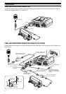
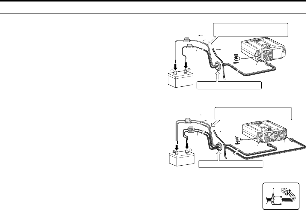
Place the DC cable the wall of the engine compartment
securely. Avoid applying excessive heat, vapor and water to
the cable.
Use a rubber or plastic grommet so that the cable
does not directly touch the vehicle chassis.
Body
DC
DC
13.8V
13.8V
1
DC 2 13.8V
AT
G
ND
G
ND
GND
2
2
1
DC IN 1
DC IN 2
Place the DC cable the wall of the engine compartment
securely. Avoid applying excessive heat, vapor and water to
the cable.
Engine compartment
Passenger
Compartment
Body
Use a rubber or plastic grommet so that the cable
does not directly touch the vehicle chassis.
Red (+)
Black (–)
12 V battery
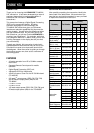
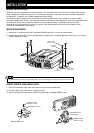
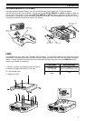
DC POWER CABLE CONNECTION
Connect the DC power cable directly to the vehicle’s
battery terminals using the shortest route. Do not use
the cigarette lighter socket! The current rating of the
cigarette lighter socket is too small to operate the
transceiver. Ensure to use a 12 V vehicle battery
which has sufficient current capacity. If the current is
insufficient, the display may darken during
transmission or the trasceiver may work
intermittiently. If you use the transceiver for a long
period when the vehicle battery has not been fully
charged or when the engine has been stopped, the
battery may become discharged in a short time and
will not have sufficient reserves to start the engine.
Avoid using the transceiver under these conditions.
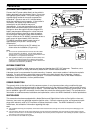
Keep in mind that the TS-480SAT transceiver draws a
peak current of approximately 20.5 A and the
TS-480HX transceiver draws a peak current of
approximately 41A (20.5A + 20.5A) during
transmission.
• Attach the line filter(s) to the DC cable(s) as
shown after the installation (E-type only).
Note:
◆
Do not use two separate batteries to connect each DC cables
from the transceiver (TS-480HX). The DC voltage difference
between DC IN 1 and DC IN 2 connectors at the transceiver must
be within DC 1.0 V to operate the transceiver.
◆
Two supplied DC cables (or two optional PG-20 DC cables) must
be used. Using different length and/ or different gauged cable
could result in a voltage difference between DC IN 1 and DC IN 2
connectors at the transceiver (TS-480HX).
TS-480SAT
TS-480HX
E-type only