


29
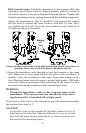
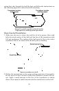
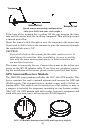
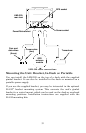
Speed sensor mounting configuration:
side view (left) and rear view (right.)
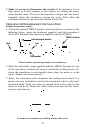
If the base of the transom has a radius, fill the gap between the tran-
som and the sensor with the caulking compound. This will help ensure
a smooth water flow.
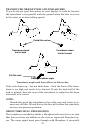
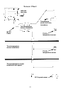
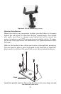
Route the sensor's cable through or over the transom to the sonar unit.
If you need to drill a hole in the transom to pass the connector through,
the required hole size is 7/8".
CAUTION:
If you drill a hole in the transom for the cable, make sure it is lo-
cated above the waterline. After installation, be sure to seal the
hole with the same marine grade above- or below-waterline seal-
ant used for the screws.
The sensor is now ready for use. Connect the sensor to the in-line con-
nector on the MY-4X adapter cable. If you have any questions concern-
ing the installation of the sensor, please contact your local boat dealer.
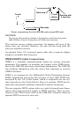
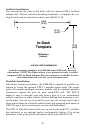
GPS Antenna/Receiver Module
The LMS-320 series package includes the LGC-12w GPS module. This
device contains the unit's external antenna and receiver for GPS and
WAAS signals. The antenna/receiver module comes with a 25-foot ex-
tension cable. This module can be mounted on a flat surface or pole, or
a magnet is included for temporary mounting on any ferrous surface.
(The LGC-12s GPS module sold with earlier Lowrance equipment will
work with your unit, but it will not receive WAAS signals.)
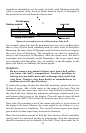
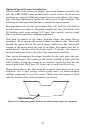
LGC-12 Module, bottom view (left) and top view (right).
Transom
Bottom of hull
Bottom of hull