


Special
Note: The
stylus
may
be
damaged
if the
transport
assembly
is
pulled
down
unless
the
stylus
has been
moved to the
back side of the
platen.
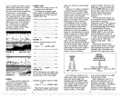
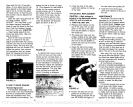
4. Pull out and
down on the tab
at the
top
center
of the
platen
assembly
to
expose
the
paper
spools.
(See Figure
26).
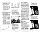
5. To
remove the full
take-up
roll
and the
empty supply
spool,
press
the two metal
tabs
together
on the
top
of
the
transport
assembly,
and
pull
out and
down on
the
paper
retainer.
(See
Figure 24).
The
full
take-up
roll can now be
easily
removed from the
paper
core
shafts.
(See
Figure
27).
6. Pull the
empty
supply
core
from the
right
side in
the same
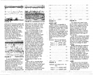
manner Install the
empty
core
onto the
take-up
shaft.
(See
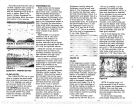
Figure 29). Align
the two
notches in the core with
the
tabs on
the lower
take-up
spool.
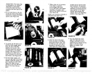
7. Slide a
fresh roll of
Lowrance
chart
paper
in
position
on the
supply
side shaft
on the
right
side of the
platen
assembly.
The
paper
must
spool
off the
bottom of
the roll.
(See Figure
30).
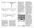
NOTE: Use Lowrance LPG-605 or
LPG-606 chart
paper only.
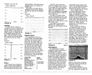
8. Draw the
end of the
paper
across the face
of the
platen,
around the friction
roller,
over
the
take-up core,
and
tape
it
squarely
to the
take-up
core.
(See Figure 31).
Small
pieces
14
15
of
tape may
be stored inside
the
housing
for
this
purpose.
Close the
top
of the
transport
assembly by
pressing
the two
tabs
together
on the
paper
retainer and
returning
the
retainer back to the
operating
position.
(See Figure
32.)
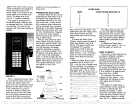
•0
FIGURE 26
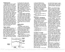
9. Turn
the small knob at
the
upper
left hand side of
the
transport
assembly
to
put
a
small
amount of
tension on the
paper.
It should be
snug
against
the
platen. (See
Figure
33.).
FIGURE 29
FIGURE 31
FIGURE 33
PDF compression, OCR, web-optimization with CVISION's PdfCompressor