


the sonar can
separate
two tar-
gets
that are 11/2 inches
apart.
This
is considered
good
resolution.
However,
if a sonar'
pulse length
was 500
micro-seconds,
then the
sonar could
only separate targets
that are at least 12 inches
apart.
That is
why
it is so
important
to
pick
a sonar unit that
gives you
the
capability
to
change
to narrow
pulse lengths
for
good
resolution.
The X-16 allows
pulse lengths
down to 30 micro-seconds or one
inch!
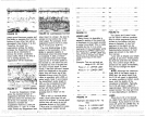
SECOND ECHO A second echo
can
appear
on the
display
at
roughly
twice the
depth
of the
actual
bottom
signal.
This is
caused
by
the transmitted
signal
travelling
thru the
water, reflecting
off of
the
bottom,
returning
to the
surface,
reflecting
off the
surface,
hitting
the bottofti once
again,
and
finally
striking
the surface and the
transducer.
Actually,
the sonar
sig-
nal can do this
many
times as
you
can see if
you
are in shallow water
and turn
up
the
sensitivity.
Some-
times
three, four,
or more echoes
can be
displayed.
SENSITIVITY
The
ability
of a
sonar unit
to
display targets.
If a
unit can
display
small
targets deep
in the water
or
very
small
detail,
then it is said
to have
high
sensitivity.
A
sensitivity
control
adjusts
the
level of the receiver for
different
conditions. Also called
gain.
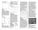
SCALE
Depth markings printed
on
or near the chart
paper
These
can be shown in
feet, fathoms,
or
meters.
Often confused with
Range.
SIGNAL-TO-NOISE
RATIO The
noise level divided
by
the
signal
level in a circuit is
expressed
by
the term
signal
to noise ratio. In
sonar,
a
high signal
to noise ratio
is desirable because
less noise
suppression
is
required
and it is
easier for the unit to
display only
the true
signals returning
from the
targets,
rather than a mixture of
signals
and noise.
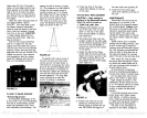
STYLUS This is the fine wire that
does the actual
marking
on a
graph
recorder's
paper.
A
high
voltage
is
applied
to the
stylus
which causes it to burn
through
the white outer
coating
of the
paper, exposing
the black carbon
underneath. Use care when han-
dling
a
stylus.
Never touch
it when
the unit is
operating.
STYLUS SKIP This is a
condition
that occurs when the
stylus
doesn't contact the
entire surface
of the chart
paper.
It then leaves
gaps
in the record where
the
stylus "skip'
over
spots.
Usually,
the
problem
can be rectified
by
removing
and
bending
the
stylus
into the
proper
shape, although
sometimes
it is caused
by
a worn-
out
stylus
which must then
be
replaced.
SUPPRESSOR
A Lowrance
exclusive,
patented
probess
to
eliminate
noise from a sonar unit's
display.
It works on the
principal
that noise
pulses
are
typically
short
in duration.
By increasing
the transmitters
pulse length,
and
tracking
it with the
receiver,
the
short noise
pulses
are cancelled
out.
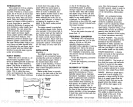
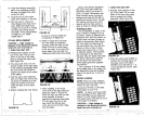
STYLUS BELT A belt that travels
over two motor driven
pulleys.
It
typically
has a holder that retains
the
stylus
and a
magnet
on the
opposite
side that
triggers
thd
transmitter.
Pulse
Alternate Transmit and Print
Paper
Save
Print
Intensity
Loran Interface
Power Booster
Summary
of Commands
Glossary
Accessories
23
24
24
25
26
26
26
29
SPECIFICATIONS
Dimensions
(with gimbal mount)
Dimensions
(instrument only)
Weight
Chart
Paper
Transmitter
Frequency
Pulse Width
(Adjustable)
1 0¼"W x 8¼"H x 65/s"D
12¼"W
x
9"H
x
65/ct
8.5
pounds
LPG-606
(2)
4" x 50' roll
192 kHz
30
s
-
2000
p.s
1600 watts
p-p
200 watts RMS
Output
Power
Receiver
Sensitivity
Chart
Speed
Voltage Range
Current Drain
Fuse
—85 db
.10 -3.0 in/mm
10
-
15 vdc
amps, approximately
4
amp
28
1
PDF compression, OCR, web-optimization with CVISION's PdfCompressor