


INTRODUCTION
The Lowrance X-16 is a
highly
sophisticated recording depth
sounder Thanks to a micro-com-
puter,
the X-16 can do more than
any
other sonar unit in its
price
range plus many
that cost much
more.
Using
the
waterproof key-
board,
full control of the
system
is
at
your fingertips
to meet the
changing
demands of
varying
bot-
tom
conditions,
water
depth,
and
boat
speed.
You can select the
unit's
sensitivity,
discrimination
level, upper
and lower
depth
range, paper speed, GRAYLINE,
and
many
more
features. The
patented
Lowrance variable
sup-
pression system
combined with
the new Discrimination feature not
only
filters out false
signals
with-
out
distorting
the real
ones,
but is
syncronized
with the GRAYLINE
function to
provide
clear
signals
under all
conditions.
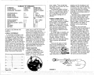
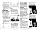
HOW IT WORKS
When the
unit is turned
on,
an
electronically regulated
motor
drives a
lightweight
belt located at
the
right edge
of the
recording
paper
The
stylus
is
attached to
this belt. When the
stylus
is at the
top
of the
paper
a small
mark is
made. This is called the zero
mark,
and
represents
the
surface
of
the water. The
stylus
continues
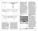
FIGURE 1
GRAPH
PAPER
to move
down the
edge
of the
paper
while
the sound
pulse
is
traveling
through
the
water,
and
when an echo
is
detected,
the
stylus
makes
another mark on the
paper.
The
depth
of the
object
which reflected the
echo can be
read in
feet, fathoms,
or meters
by
comparing
its location
on the
paper
to the
depth
scale
printed
on the
paper.
The
paper speed
is controlled
by
a variable
speed
motor
During
one revolution of the
stylus
belt,
a
very
narrow mark
will be made
by
the flexible
stylus,
but the
paper
will move a small amount before
the next revolution. Each mark will
blend into the one before so that a
composite picture"
of the
target
will be
made,
one
tiny
mark at a
time.
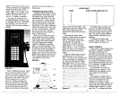
INSTALLATION
Mounting
—
The
depth
sounder
may
be
installed
in
any
convenient
area,
provided
the unit can be tilted for
the best
viewing angle.
Holes
in
the bracket base allow wood
screw or bolt
mounting.
A wood
stiffener
may
be
required
on the
back of thin
fiberglass panels
to
support
the unit.
Make certain there is
enough
room on the back side of the unit
to attach the
power
and trans-
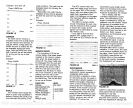
PULLEY
DRIVE
-STYLUS
DRIVE
BELT
•
STYLUS
PULLEY
on the X-16.
Because the
transmitted
power
is
greater,
stronger signals
are transmitted
into the water. This will
increase
the
depth range
of the unit and
the
signal
to noise
ratio, plus
the
ability
to see small detail is
enhanced. For installation
instructions on the LPB-1
92,
read
the owner's manual included with
the
power
booster.
To turn the
power
booster
on,
press
12- 2nd -5.
To turn
the
power
booster
off,
press
2nd
-
8.
FREQUENCY
CONVERTER
The Model LXC-16
frequency
converter allows the
X-16 to use
either a 50 kHz or 192 kHz
operating frequency
at the
discretion of the
operator.
It can
be
switched from 192 to 50 kHz at
any
time
by using
the
keyboard.
For
installation
instructions,
see
the
owner's manual included with
the LXC-16.
To turn
the
frequency
converter
on, press
2nd
-
5.
To turn
the
frequency
converter
off, press
2nd
-
8.
GLOSSARY OF
TERMS
CAVITATION Air bubbles
trapped
against
the transducer.
This is
typically
caused
by
an
improper
transducer installation. Aluminum
boats in
particular
have
problems
with cavitation. The
problem
is
most
evident when
travelling
at
high speed.
Air bubbles are cre-
ated
by
rivets, strakes, ribs,
or
other
objects
which then
pass
over
the face of the
transducer. For the
proper operation
of the
transducer,
it must have solid
contact with the
water at all times.
MICRO-SECOND
Unit of mea-
sure. One micro-second is
equal
to 0.001
second. Used in sonar to
measure the amount of time
the
unit is
transmitting.
Abbreviation:
W5.
NOISE
Any
undesired
signal.
Noise can
show
up
on a
graph
recorder as small
dots or lines
randomly
scattered across the
paper.
It can be
caused
by
electri-
cal sources such as
alternators,
spark plugs, improper
wiring,
or
by
mechanical
sources,
air
bubbles
passing
over the
face of the
transducer,
vibration of the
engine,
or
a loose transducer
mounting.
OUTPUT POWER The amount
of
electrical
energy applied
to the
transducer
by
the transmitter.
Expressed
in
wafts,
typically
the
higher
the
output power
a sonar
unit
has,
the
deeper
it can
read,
and
smaller detail can be shown.
POWER
BOOSTER A device
which
connects to the transducer
jack
of the sonar
unit and
increases its
output power.
PULSE LENGTH
The
length
of
time that the sonar unit
transmits
a
pulse
of sound
into the water
This
period
of time is
very
short
and is
usually
referred to in micro-
seconds. Also called Pulse Width.
RANGE Maximum
depth
that a
sonar
unit is set to
display.
For
example,
a
range setting
of 0-60
feet on a
graph
means that the
maximum
depth
that can be dis-
played
before
the bottom echo
drops
off the chart
paper
is 60
feet.
RESOLUTION
The
ability
of a
sonar unit to
separate targets.
This
ability
is
determined
by
the
pulse length
of the unit. If
the
pulse length
is
very short,
50
micro-seconds for
example,
then
27
2
PDF compression, OCR, web-optimization with CVISION's PdfCompressor