


be used to
help
alleviate
this
condition.
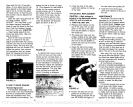
LORAN-C
INTERFACE
A remarkable
advantage
of the
X-16 is its
ability
to
print
Loran-C
coordinates in either
Time Differen-
ces
(ID's)
or
Latitude and
Longi-
tude.
(NOTE:
The
X-16 has been
designed
to
use
only
the Lowrance
Loran-C
receiver.)
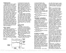
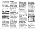
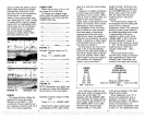
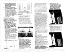
To connect the
Loran to the
X-16,
simply splice
the
white and black
wire on the X-16's
power
cable to the
white and black
wire on the
Loran-Cs
power
cable.
(See Figure
2 on
page 3.)
After the
proper
connections have
been
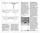
.i.::
I—
I1iI
24.0 ——I
p6.0
—— —
26.0
B.0—
48.0—
4
60.Ofl—
Figure
46
made,
turn on both the Loran and
the X-16. After the Loran has
acquired
the
signals, press
2nd
-
0.
The Loran coordinates will imme-
diately
be
printed vertically
down
the
paper.
Either Latitude and
Longitude
or Time Differences
(TD's)
will be
printed
on the
paper
depending
on the mode the Loran
is in. If 2nd
-
0 is
pressed
and no
Loran is
connected,
the unit will
stop pulling paper
and
printing
for
approximately
four seconds.
POWER BOOSTER
A
power
booster,
Model
LPB-192,
is available that will
increase the transmitter's
output
power
of the X-16. It can be
turned on or off
by
the
keyboard
26
ducer
cables. There should also
be
enough
room to allow the front
panel
door to
open.
If the desired location is closer
than 18" to a
magnetic compass,
a
trial
run should be made with the
unit in
operation
to be sure that
the
compass readings
are not
affected.
POWER CONNECTIONS
Twelve volt DC
power
for the
depth
sounder should be
supplied
by
the boat's 12 volt electrical
system.
The
power
cable
may
be
attached to an
accessory
or
power
buss,
but if
you
have
problems
with electrical
interference,
the
cable should be attached
directly
to the
battery.
If a
longer
cable is
required,
use
ordinary
#18
lamp
cord available
at
any
hardware or electrical
sup-
ply
store.
Splices
should be
soldered, however,
if this isn't
done,
then use
crimp-type
splices.
Tape
all
splices
with
electrical
tape.
There are two
types
of noise
that can be introduced into the
sonar
system
if an
improper
installation is
made,
electrical
noise
picked up by
the transducer
or
power
cable,
and acoustic
noise
picked up by
the transducer.
Acoustic noise is caused
by
water
turbulence,
air bubbles
FIGURE
2
3
passing
over the
transducer,
and
cavitation where a
partial
vacuum
is formed
by
the flow of water. This
noise is minimized
by following
carefully
the transducer installation
instructions
concerning
location of
the transducer.
Electrical noise is caused
mainly
by
the boat
engine's ignition sys-
tem.
Keep
the transducer cable
and
power
cable
away
from
possi-
ble sources of electrical inter-
ference.
Again,
connect the
power
cable
directly
to the
battery
if
possible,
not the boat's
wiring
harness.
Cavitation and
electrically
induced
noise can be
generated
if
a careless installation has been
made,
but
the
Suppressor
circuit
and Discrimination is effective in
combatting
both.
Before initial
use
or after
prolonged storage,
better
water-to-transducer
contact will
be
made
if the face of the transducer
is washed
with
mild
detergent
and
warm
water. Positive contact with
the water is essential
to reduce
cavitation
noise caused
by
bub-
bles on the transducer face.
An in-line fuse holder with a 4
amp
fuse is
supplied
with the
X-1 6. Be certain to install this as
close to the
power
source
(such
as the boat
battery
or
power buss)
as
possible.
This will
protect
both
the sonar unit and the
power
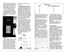
SUMMARY
OF COMMANDS
COMMAND
CLEAR ENTRY
ALTERNATE TRANSM IT
FUNCTION
CLEAR
ON/OFF
DISCRIMINATION
PAPER SAVE
PAPER SPEED
POWER BOOSTER
PRESS
KEY:
CLEAR ENTRY
UPPER
& LOWER
LIMIT
0-4
0-7
0-7
ON/OFF
-
DISC
-
2nd
-
6
-
PAPER SPEED
2nd
-
5,
ON/2nd
-
7,
OFF
PRINT INTENSITY
SUPPRESSOR
SURFACE CLARITY
(SCC)
FEET
0-2
0-7
0-7
FATHOMS
METERS
ON
-
2nd
-
LINES
-
2nd
-
9
-
SCC
ON
ON
2nd
-
1
2nd
-
2
2nd
-
3
OFE
(Negative)
PDF compression, OCR, web-optimization with CVISION's PdfCompressor