


C656M-E (4/07) 19
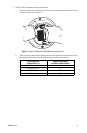
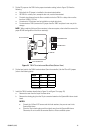
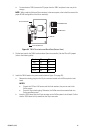
• To unterminate a TXB-V, remove the P2 jumper from the TXB-V and place it over one pin for
storage.
NOTE: When combining Pelco and Vicon receivers in the same system, refer to the Vicon manual for
proper RS-485 configuration of the Vicon receiver(s).
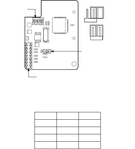
Figure 18. TXB-V Termination and Baud Rate (Bottom View)
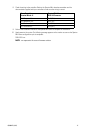
4. Set the baud rate for the TXB-V translator board (from the controller). Use the P3 and P4 jumpers
(refer to the following table).
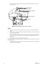
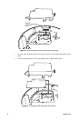
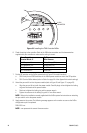
5. Install the TXB-V board on the power module (refer to Figure 19 on page 20):
a. Remove the shorting plug from the 16-pin connector located on the ExSite system’s circuit
board.
NOTES:
• Discard the 6-32 and 4-40 screws and their lock washers; they are not used in the
ExSite system.
• Save the 16-pin shorting plug. Otherwise, the ExSite cannot be converted back to a
Pelco-controlled system.
b. Insert the TXB-V board into the 16-pin connector on the ExSite system’s circuit board. Confirm
that the TXB-V board is fully seated into the 16-pin connector.
Baud P3 P4
600 OFF OFF
4800* ON ON
9600 OFF ON
19.2K ON OFF
*Factory default.
16-PIN CONNECTOR
P2 JUMPER
P3 & P4 JUMPERS
P2 UNTERMINATED
P2 TERMINATED