


C656M-E (4/07) 7
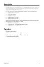
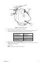
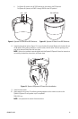
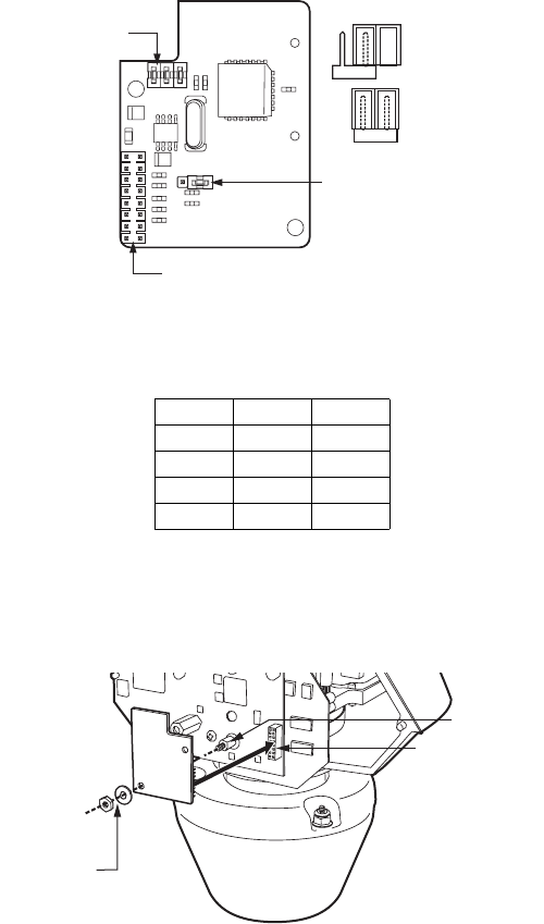
Figure 2. TXB-V Termination and Baud Rate (Bottom View)
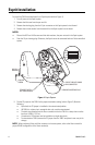
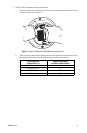
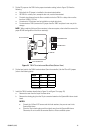
6. Set the baud rate for the TXB-V translator board (from the controller). Use the P3 and P4 jumpers
(refer to the following table).
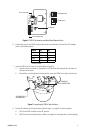
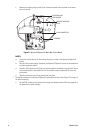
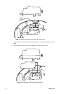
7. Install the TXB-V on the Esprit circuit board (refer to Figure 3):
a. Insert the 16-pin connector on the bottom of the TXB-V into the mating 16-pin connector on
the Esprit circuit board.
b. Reinstall the nut and washer on the standoff to secure the TXB-V to the Esprit circuit board.
Figure 3. Installing the TXB-V into the Esprit
8. Set the DIP switches on the Esprit system (refer to Figure 1 on page 6 for switch location):
a. SW1: Set all SW1 switches to the OFF position.
b. SW2: Set the Esprit address (refer to Table A on page 24 of the Appendix for switch settings).
Baud P3 P4
600 OFF OFF
4800* ON ON
9600 OFF ON
19.2K ON OFF
*Factory default.
16-PIN CONNECTOR
P2 JUMPER
P3 & P4 JUMPERS
P2 UNTERMINATED
P2 TERMINATED
STANDOFF
16-PIN CONNECTOR
STANDOFF NUT
AND WASHER