


EXTERNAL SHOW CONTROLLER CONFIGURATION
40
APPENDIX B
EXTERNAL SHOW CONTROLLER
C
ONFIGURATION
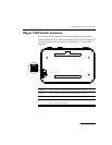
See Connecting an External Show Controller on page 17.
Electrical
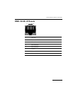
The RS-232 serial port connections on the iPlayer 3 are DB9F
connectors, labeled
SERIAL 1 and SERIAL 2. The following pinout
information applies to each DB9F connector:
The other pins are unconnected.
See Serial Port: DB9F Pinouts on page 20.
Note: +5 VDC is provided on pin 4 (normally the DTR pin).
Other devices can use this voltage provided they draw no
more than 50 mA. If the voltage on pin 4 is not desired, it
can be disabled by moving configuration DIP switch 1 (for
serial port 1) or DIP switch 2 (for serial port 2) to the OFF
position.
2 Transmit data
3 Receive data
4 +5 VDC
5 Ground