


17
EXTENSION ANALOG OUTPUT
4
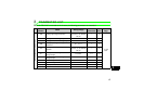
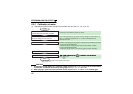
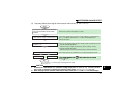
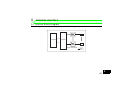
(2) Outputting different select signals from terminals AM0 and AM1 (Pr. 309 = 1 or 11)
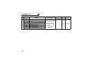
CAUTION
1. If calibration is made without "21" (reference voltage output) set in Pr. 306 or Pr. 310, terminals FM/AM of
the inverter is calibrated. To calibrate the extension analog output, always set "21" in Pr. 306.
2. When the plug-in option used was remounted on other inverter, use Pr. 323 and Pr. 324 to calibrate again.
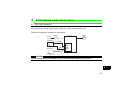
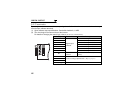
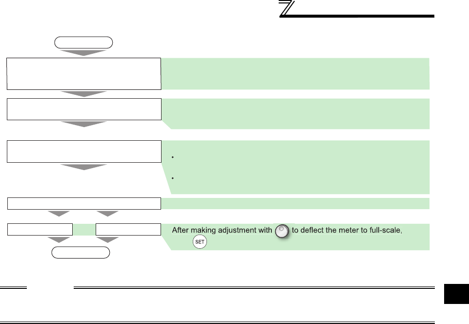
START
At this time, check that the polarity is correct
At this time, the following analog signal is actually output and deflects the meter.
<across terminals AM0-AMC>
Maximum output voltage set previously (factory setting: 10VDC)
<across terminals AM1-AMC>
Maximum output current set previously (factory setting: 20mADC)
Run the inverter
The inverter may be run in either the PU or external operation mode.
END
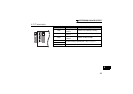
Terminal AM0 Terminal AM1
Connect a DC voltmeter (or DC ammeter)
across terminals AM0 (or terminal AM1)
and AMC.
Set "21" (reference voltage output) in Pr.
306 and Pr. 310.
press to set.
If the meter needle does not point to 0 when voltage or current input is 0,
use Pr. 323 AM0 0V adjustment or Pr. 324 AM1 0mA adjustment to
calibrate the meter
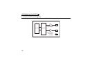
Use Pr. 323 (or Pr. 324) to calibrate the
meter when the voltage (current) input is 0.
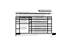
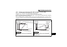
Use Pr. 900 to set
Use Pr. 901 to set
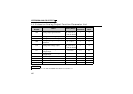
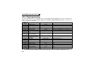
In Pr. 306 and Pr. 310, set the types of the signals to be output.
(Refer to page 18.)