


24
DIGITAL OUTPUT
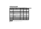
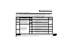
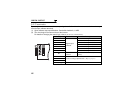
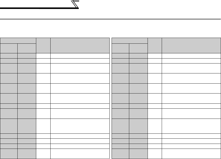
5.4 Output Signal List
For details of signal definitions, refer to Pr. 190 to Pr. 196 Output terminal function selection of the inverter
manual (applied).
Setting
Signal
Name
Function
Setting
Signal
Name
Function
Positive
Logic
Negative
Logic
Positive
Logic
Negative
Logic
0 100 RUN Inverter running 15 115 FUP PID upper limit
1 101 SU Up to frequency 16 116 RL
PID forward/reverse rotation output
2 102 IPF
Instantaneous power failure/
undervoltage
17 MC1
Commercial power-supply
switchover MC1
3 103 OL Overload alarm 18 MC2
Commercial power-supply
switchover MC2
4 104 FU Output frequency detection 19 MC3
Commercial power-supply
switchover MC3
5 105 FU2
Second output frequency
detection
25 125 FAN Fan fault output
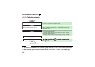
7 107 RBP Regenerative brake prealarm *1 26 126 FIN Heatsink overheat pre-alarm
8 108 THP
Electronic thermal relay function
prealarm
45 145 RUN3
During inverter running and
start command is on
10 110 PU PU operation mode 46 146 Y46
During deceleration due to
instantaneous power failure
(retained until release)
11 111 RY Inverter operation ready 47 147 PID During PID control activated
12 112 Y12 Output current detection 64 164 Y64 During retry
13 113 Y13 Zero current detection 70 170
SLEEP
During PID output suspension
14 114 FDN PID lower limit 71 RO1
Commercial-power supply side
motor 1 connection RO1
*2