


18
EXTENSION ANALOG OUTPUT
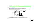
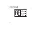
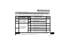
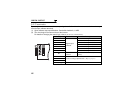
4.5.3 Output signal setting
Set the output signals to be monitored. Set Pr. 306 to output the same signal from terminals AM0 and AM1
and Pr. 306 and Pr. 310 to output different signals. For details of signal definitions, refer to Pr. 54 and Pr. 158
of the inverter manual (applied).
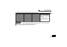
*1 Setting can be made only for the 75K(01800-EC, S75K-CH) or more.
*2 The setting depends on capacities. (55K (01160-EC, 55K-CH) or less/75K (01800-EC, S75K-CH) or more.)
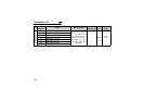
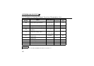
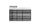
Pr. 306/Pr. 310
Setting
Types of Monitor Increments Full-Scale Value
1 Output frequency 0.01Hz Pr. 55
2 Output current 0.01A/0.1A *2 Pr. 56
3 Output voltage 0.1V 800V
5 Frequency setting 0.01Hz Pr. 55
6 Running speed 1(r/min) The value converted with the Pr. 37 value from Pr. 55.
8 Converter output voltage 0.1V 800V
9 *1 Regenerative brake duty 0.1% Pr. 70
10
Electronic thermal relay
function load factor
0.1% Electronic thermal relay function operation level
11 Output current peak value 0.01A/0.1A *2 Pr. 56
12
Converter output voltage
peak value
0.1V 800V
13 Input power 0.01kW/0.1kW *2 Rated inverter power × 2
14 Output power 0.01kW/0.1kW *2 Rated inverter power × 2
17 Load meter 0.1% Pr. 56
21 Reference voltage output
24 Motor load factor 0.1% 200%
50 Power saving effect
Variable according to parameters
Inverter capacity
52 PID set point 0.1% 100%
53 PID process value 0.1% 100%