


4.3 ASSEMBLY OF FIRST STAGE
1. The part number for each regulator kit can be found in Sherwood’s Tools, Repair Kit and
Accessories - Assembly & Maintenance Guide. The kits contain the minimumparts that must
be replaced at every annual service interval. The technician will also evaluate the condition of
all other parts to determine replacement needs. The kit number for the regulators covered in
this manual is 4000-15. The Nitrox kit for these models is p/n 4000-15N
2. Before installing new O-rings on the piston and moving orifice, lubricate the O-rings with LTI
Crystolube (Sherwood p/n SW-MS150). Installation of the small O-ring on the piston is
made much easier by using the brass-colored Sherwood O-ring installation cone (p/n TL106).
Place the cone over the tip of the piston. Slide the lubricated O-ring over the cone until it slips
into the piston groove.
3. Place the new piston seat on a clean piece of paper on a hard flat surface. Press the piston tip
firmly over the seat until it is fully installed. The piston is now rebuilt and ready for installation.
4. Use the Sherwood installation cones to prevent damage to the new O-rings during installation
onto the moving orifice. Use the black O-ring installation cone (p/n 29-TL108) to install first the
new O-ring and then the used backup washer onto the wider groove on the moving
orifice. Postion them so that the black O-ring is closest to the wide end of the moving orifice.
Use the green O-ring installation cone (p/n 38-TL107) to install the O-ring into the groove
closest to the pointed tip of the orifice.
5. Using a greased soft probe,
lightly lubricate the first 1/8” of the small bore in the body
where the small piston and moving orifice O-rings seal.
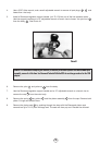
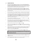
6. With your finger, push the moving orifice assembly, pointed orifice end first, into the yoke end
of the main body as far as possible. Place the inlet filter , rough side up, on top of the
moving orifice. Place the retaining ring or star washer on top of the filter. Push the retaining
ring or star washer firmly into place with a dowel or screwdriver.
7. Replace the cleaned and lightly lubricated O-ring on the body .
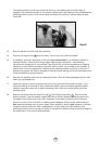
8. Install the piston assembly squarely into the cap . If any shims were found when the
regulator was disassembled, place them over the piston stem. Then place the main spring
over the piston stem.
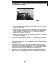
9. Install the cap assembly onto the body. Hand-tighten the assembly as tightly as possible, then
install the Sherwood regulator support handle into one of the low pressure ports. Using a 15”
adjustable wrench or a bench vice to hold the cap, tighten the cap onto the body until it
bottoms on the thread.
Do not tighten further.
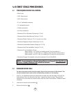
10. Using your index finger, install the clean and dry one-way bleed valve into the body.
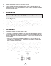
11. Lightly lubricate the body yoke nut threads with grease, and install the yoke and the yoke
nut onto the body.
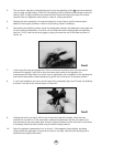
12. Using the regulator support handle (p/n TL113) in one of the L. P. pressure ports of the body
and a 15” adjustable wrench, tighten the yoke nut snugly (see Photo #1).
9
21
7
13
2
18
3
25
23
12
10
11
19
15
8
NOTE
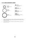
: If you use the bleed valve with the Sherwood logo molded into it P/N 3106-06 you will notice a
“dot” molded near the right side of the logo. Install the bleed valve with the “dot” oriented closest to the
inlet of the regulator (toward the yoke).