


13
a. Place the cover assembly with the purge button logo face down on a clean flat surface.
b. From the inside of the cover assembly, push the four barbed tabs holding the purge button
assembly in place in towards each other. This will release the purge button
assembly from the cover.
c. If only the label insert was purchased for installation, carefully remove the old label
insert from the purge button with a thin flat-blade screwdriver, and install the new
colored label insert in its place.
d. Reverse the disassembly procedure to reassemble the case assembly with the new color
logo installed.
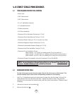
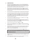
6. Gently remove the diaphragm from the case. Hold the diaphragm up to a light source.
Gently stretch the diaphragm and look for tears or pinholes. If any are found, replace the
diaphragm. Otherwise, the diaphragm can be reused. If you are repeatedly tearing diaphragms
during this visual inspection, you are using too much force. You cannot return diaphragms torn
in this way for warranty credit.
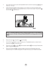
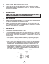
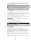
7. Clamp the Sherwood modified 3/4” deep socket (p/n TL118) in a bench vise. Lower the lever
into the socket until the 3/4” hex of the lever support is engaged in the socket. Use a
13/16” wrench to loosen and remove the orifice housing .
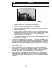
8. Use the Sherwood in-line adjusting tool (p/n TL102) to back the adjusting orifice out of the
orifice housing until the threads disengage. Remove the in-line adjusting tool, and push the
adjusting orifice the rest of the way out of the orifice housing with the Sherwood Plastic Probe
(p/n TL111).
9. Remove the O-ring from the adjustable orifice.
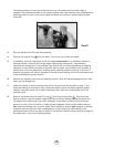
10. Before removing the exhaust valve from the case, bend it over as far as it will go from the
top, bottom, left, and right sides. If it fails to snap back quickly, and does not lie perfectly flat
against the case, the valve should be replaced. If it does snap back satisfactorily, remove it and
inspect the sealing edges. If they appear smooth, and the locking tab on the nipple is good,
the valve can be reused.
11. Remove the spacing washer , and the O-ring from the threads of the lever support .
Remove the lever support from the inside of the case .
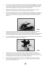
12. Normally, you will simply need to change the poppet stem seat insert to restore the second
stage to maximum performance. To change the stem seat insert , leave the lever assembly
together. With a penknife or similar object, carefully remove the old seat insert. Put the new
seat insert on a clean flat surface and lower the poppet cavity (from which the old seat insert
was removed) over the new seat insert. The new style black molded seat ( p/n 978-9BN)
should be installed with the identifying Sherwood symbol facing outward.
2
9
10
22
1
10
13
13
23
17
20
16
21
6
NOTE
: The purge button spring is located behind the purge button, with the wide end of the coil toward
the cover. Be sure to replace the spring with the wide end facing the cover.
NOTE
: Some regulators (Oasis, Blizzard, Classic) will have heat transfer fins (10B) attached to the lever
support. The modified 3/4” socket will still fit onto the lever support with the fins attached. You can leave
the fins attached throughout your servicing. If the fins are damaged and need to be replaced, use the
Sherwood 5/32” drive socket to remove and replace the two 5/32” hex head screws (10A).