


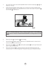
13. If parts of the lever assembly (stem, spring, lever, etc.) need to be replaced, take apart the
assembly with the Sherwood stem socket tool (p/n TL124) Clamp the stem socket tool in a
bench vice. Insert the square head of the poppet stem into the tool. With a Phillips screwdriver,
or preferably a size 0 Square Drive (Robertson Head) screwdriver, loosen the screw that
holds the assembly together.
14. Rinse all plastic and silicone parts in clean fresh water, and then blow the parts dry with
compressed air to remove any sand and dust particles.
15.
If necessary, clean all metal parts of the second stage in an ultrasonic cleaner or cleaning
solution. Remove the O-rings before cleaning any metal parts; most cleaning solutions are
damaging to the O-ring material. See Section 6.3 for recommendations on cleaning solutions.
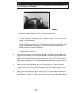
16. Inspect the case for any cracks. Look particularly closely at the area where the orifice
housing and the lever support clamp down. Replace the case if any cracks are found.
17. Inspect the orifice sealing cone (where the poppet insert seals) for any nicks, scratches, or
corrosion. Corrosion or minor scratches can be polished out using a fine-grit rubberized
polishing stick or a clean new pencil eraser. Do not apply heavy pressure when rotating the
polishing stick. Stop polishing immediately after the corrosion or scratch disappears. An orifice
will not be accepted for warranty replacement simply because it is dirty or corroded. The
technician must clean the orifice sealing surface at every service interval.
18. Blow all dust and debris out of the orifice housing with clean compressed air.
5.3 ASSEMBLY OF SECOND STAGE
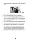
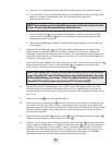
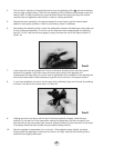
1. Re-install the cleaned and lubricated O-ring onto the adjustable orifice . Install the
adjustable orifice back into the orifice housing. Push it in with your finger as far as it will go.
2. Install the exhaust valve into the case by inserting the nipple into the small hole from the
outside of the case. Reach inside the case and pull the nipple firmly with the fingers until you
hear or feel it “click” into place. Inspect the exhaust valve to see that it is properly seated.
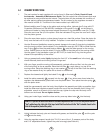
3. Install the lever assembly into the case.
4. Install the O-ring on the threads of the orifice housing. Install the spacing washer
around the outside of the O-ring.
14
NOTE
: Prior to this point, you should have cleaned and inspected all parts, following proper servicing
procedures. Do not continue until this has been done.
NOTE
: The spacing washer must be installed with the outer lip facing upward toward the orifice housing.
NOTE
:If only the lever is to be replaced, do not totally remove the screw. You can remove the lever
from under the washer by pushing the poppet into the lever support when the screw is almost all the
way out.
NOTE
: If you use an ultrasonic cleaner to clean the second stage adjustable orifice , use a plastic
container to prevent the orifice from vibrating against other metal parts which could damage the orifice seal.
7
17
23
24
20
21
9
22
8
16