


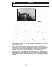
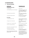
5. Screw the orifice housing onto the threads of the lever assembly. With a 13/16” wrench on
the orifice housing and a Sherwood modified 3/4” deep socket (clamped in a vise) on the hex
of the lever support inside the case, tighten the orifice housing and the lever assembly
together snugly (70 in. lbs. / 8 Nm).
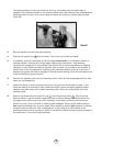
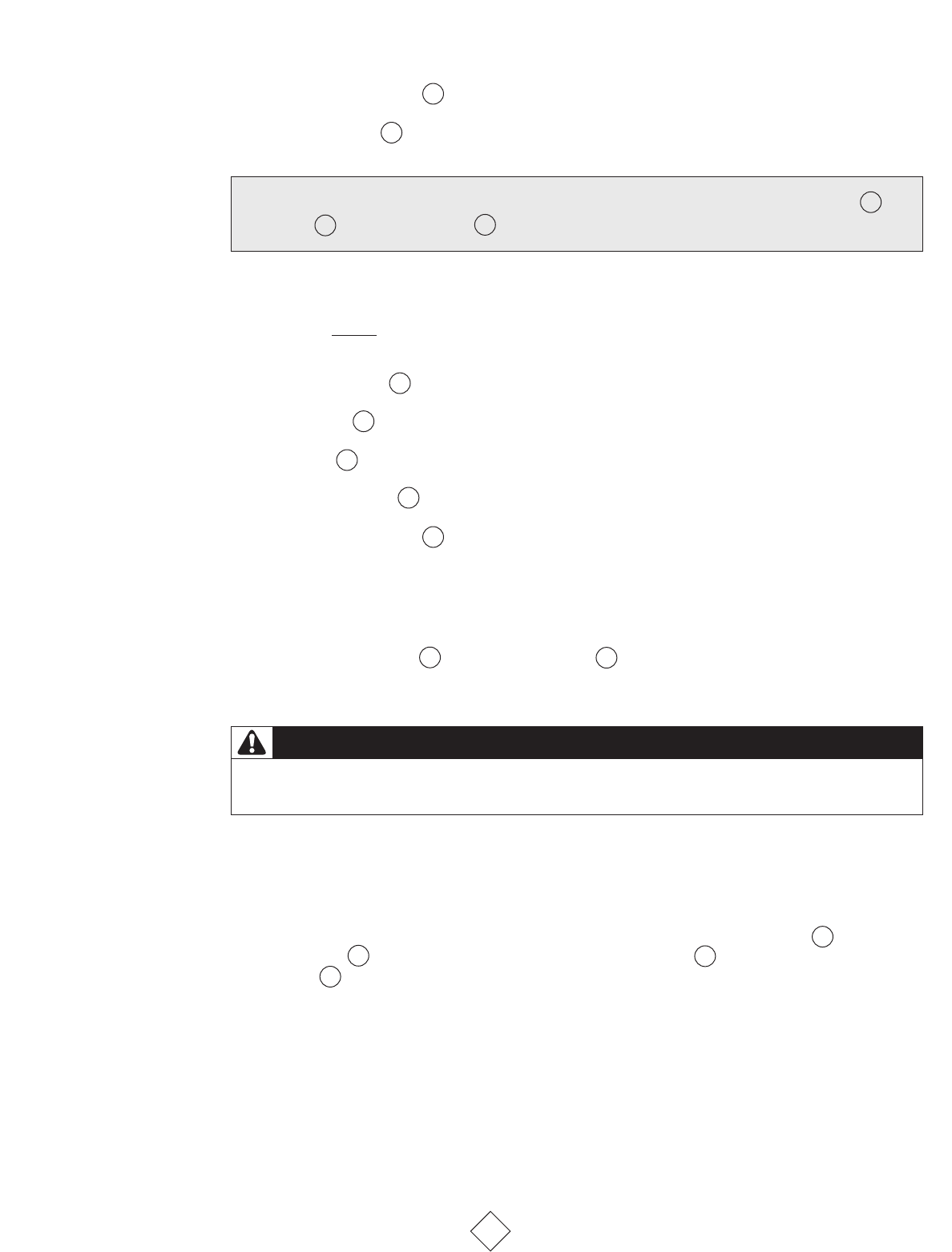
6. Install the diaphragm into the case so that it sits evenly on the ledge.
7. Install the cover onto the case by sliding it carefully and firmly into place. Keep the cover
straight so that the cover vent holes and the purge button emblem are properly aligned. Install
the bezel ring over the cover and tighten it firmly by hand onto the case.
8. Install the exhaust tee onto the case flange by sliding it up from the bottom.
9. Install the retaining screw through the screw hole in the exhaust tee and into the hole in the
case using a # 1 Phillips, or Size 0 Square Drive screwdriver.
DDOO NNOOTT OOVVEERR--TTIIGGHHTTEENN
. This screw is threading into plastic, which will hold well in service but is
easily stripped if over-tightened.
10. Install a new mouthpiece and mouthpiece tie .
11. Install one end of the hose into a serviced first stage, tighten snugly.
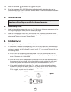
5.4 SET- UP OF SECOND STAGE
For the following adjustments, remove the cover and diaphragm.
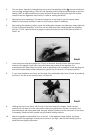
1. Install Sherwood’s in-line adjusting tool (p/n TL102) between the orifice housing and the
hose assembly . Use the tool to screw the adjustable orifice clockwise. Watch the end
of the lever as you do this. As soon as the tip of the lever begins to drop, stop turning the
tool. The slight amount of friction this operation produces between the orifice and the stem
seat will not harm the stem seat.
2. Attach the in-line tool and the second stage to its accompanying overhauled and properly
adjusted first stage, and mount on an air tank filled to between 2700 and 3500 psig (186 and
240 bar).
3.
Slowly turn on the tank valve. If you hear any leaks, determine the location of the leak, shut the
air off, and repair the leak as necessary.
15
22
10
5
4
14
15
18
19
22
6
26
9
24
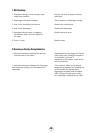
NOTE
: Do not allow lubrication (grease on fingers, or silicone over-spray) to get on the case , the
diaphragm , or the exhaust valve . This may cause slippage or deterioration of these parts.
17
16
6
NOTE
: THE FOLLOWING STEPS (6 - 10) ARE INCLUDED HERE FOR CONTINUITY. THEY MUST BE
PERFORMED AF
TER THE REGULATOR SECOND STAGE IS ADJUSTED (see 5.4 Setup of Second Stage).
WARNING
NEVER tighten the hose with more than 40 in. lbs. (4.5 joules) of torque. The inlet hose
fitting can be weakened by overtightening.