


Series 830/840/860 Instruction Manual Chapter 2 Installation
IM-83/84/86-H 2-7
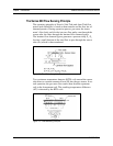
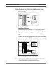
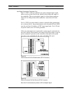
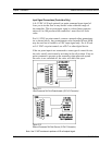
Wiring Transducers with 20-Pin Card-Edge Connectors Input
Power Connections
Figure 2-2. Input Power Connections (20-Pin Connector)
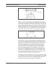
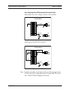
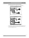
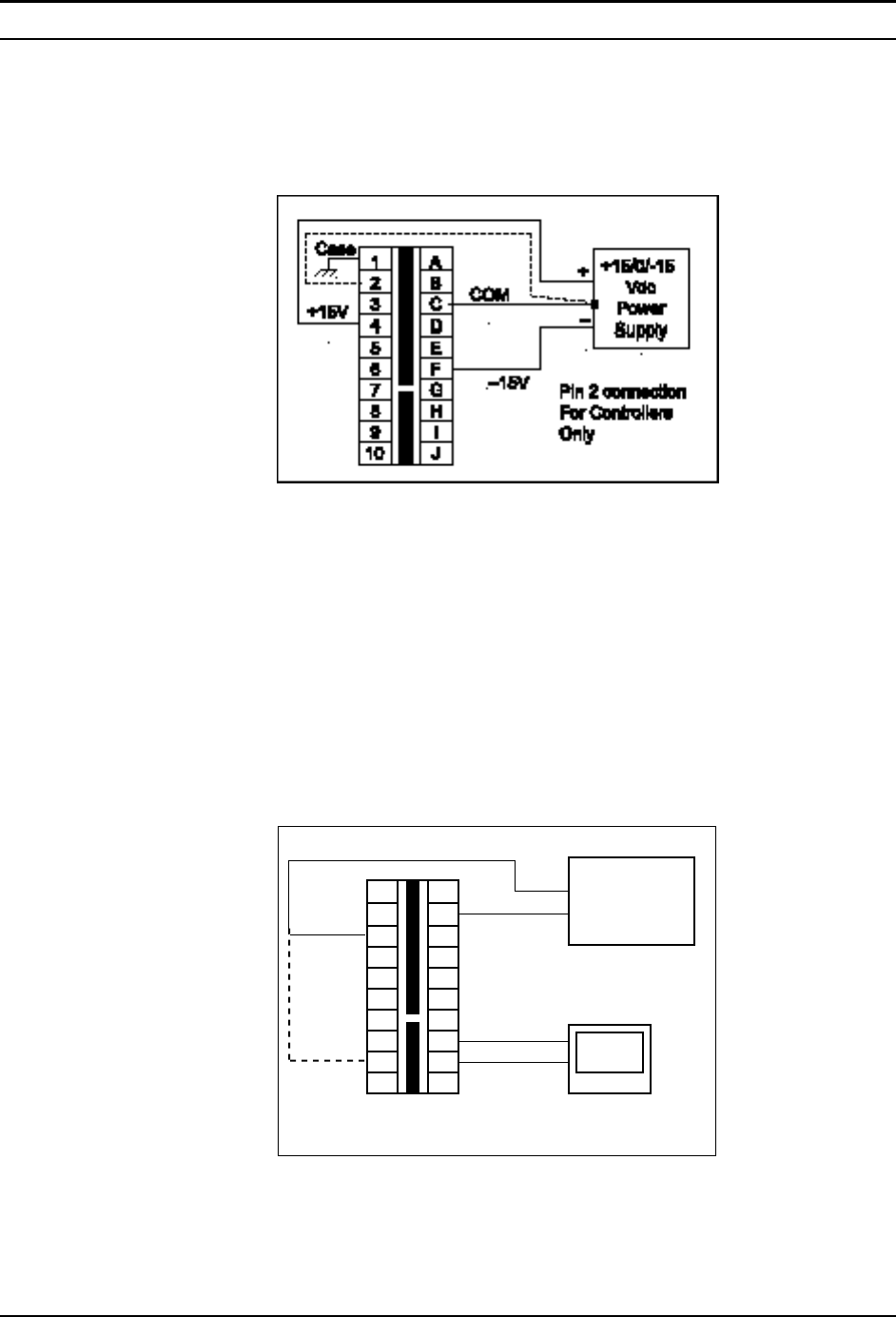
Output Signal Connections
Standard output for all transducers is a 0-5 VDC signal, which di-
rectly corresponds to the 0 to 100% mass flow full scale range.
Output signals are linear and require a minimum load resistance of
1000 Ohms (4-20 mA output 600 Ohms maximum loop resis-
tance).
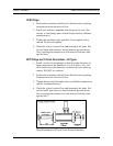
The Auto-Trak 860 allows transmission of all available input/output
signals to your computer’s RS-485 communications port (connection
details are given below). For additional information, refer to the “Auto-
Net” Software Addendum included with this manual.
1
2
3
4
5
6
7
8
9
10
A
B
C
D
E
F
G
H
I
J
Panel Meter
PLC or
Recording
Device
COM:1
Computer
RS-485 Communications
Model 860 ONLY
V or mA
V out+
COM
RS-485+
RS-485–
mA out+
+
–
Figure 2-3. Output Signal Connections (20-Pin Connector)
Notes: 1. Controllers require a separate, dedicated ground wire between pin 2 and the
power supply common to carry the valve coil current.
2. 4-20 mA output signal is ground-referenced (“non-isolated”).
Warning: Do NOT apply any external voltage to this loop.