


Series 830/840/860 Instruction Manual Chapter 3 Operation
IM-83/84/86-H 3-1
Chapter 3 Operation
This chapter covers transducer operation and controller features
available on Sierra’s Side-Trak
™
and Auto-Trak
™
models. For
more information on the advanced digital RS-485 commands
available on Auto-Trak transducers, refer to the Series 860 “Auto-
Net” Software Addendum included with this manual.
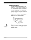
Standard output for all transducers is a linear 0-5 VDC output signal
directly corresponding to 0 to 100% of the mass flow full scale
range. For mass flow controllers an input signal of 0-5 VDC (4-20
mA optional) allows set point flow control to any desired value
within the range of the model. The input signal is a direct linear rep-
resentation of 0 to 100% of the mass flow full scale value. A 0 VDC
(or 4 mA) set point will cause a condition of 0% flow to occur and a
5.00 VDC (20 mA) set point will cause a flow condition equivalent
to 100% of flow to occur.
Mass Flow Meter Operation
When the transducer is installed and the system has undergone a
complete leak check:
1. Apply power. Allow thirty minutes of warm-up time. (When
power is first applied, the output signal from the transducer
remains fixed at a much higher than normal level until the sen-
sor warms up to its normal operating temperature range.)
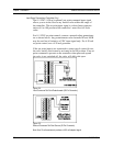
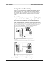
2. Turn on the gas supply. Perform an initial zero output check
(only required for first-time start ups). Set flow to zero. Connect
a digital multimeter to V+out (4-20 mA out) and COM termi-
nals.
3. Check the reading. If it is not within ±10 mV (±0.10 mA) of
zero, adjust the zero potentiometer to zero the transducer. (The
zero pot is located behind the upper metal button on the side of
the transducer or behind the swing-out plastic door.)