


Chapter 4 Maintenance Series 830/840/860 Instruction Manual
4-10 IM-83/84/86-H
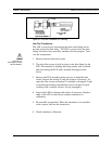
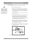
3. Unscrew the coil cover with a 11/16 inch wrench. Remove the
coil and coil enclosure. Note the location of any washers or
spacers for re-assembly.
4. The small circuit board may be separated from the main board
to ease removal of the coil. To separate, first remove the
mounting screw located in the center of the main circuit board
and carefully pull the two boards apart.
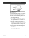
5. Remove the four 1/4-28 socket head cap screws at the base of
the valve. Separate the valve from the flow body, taking care
not to lose any small parts.
6. There are three O-rings sealing the valve assembly: one be-
tween the base and the flow body, one under the valve seat
(orifice), and one on the top adjusting screw inside the valve.
Inspect the O-rings for damage and replace as necessary. (You
should replace all O-rings whenever the valve is disassembled.)
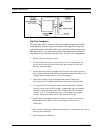
7. Inspect the valve seat and plug for corrosion or roughness and
replace as necessary.
8. Re-assemble the components. When the controller is installed
in the system, leak test the connection.
9. Adjust the valve for proper operation as given in the controller
valve adjustment procedure.