


Simrad AP26 and AP27 Autopilots
58 20221586B
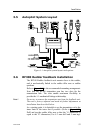
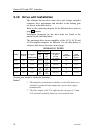
3.10 Drive unit installation
The relations between drive units, drive unit voltage, autopilot
computer, drive performance and interface to the steering gear
are shown in the tables below.
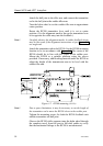
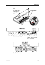
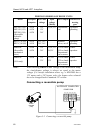
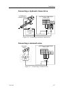
Refer to the connecting diagram for the different drive units on
page 60 onwards.
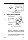
Installation instruction for the drive units are found in the
manual for the individual units.
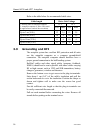
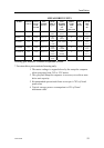
The maximum drive current capability of the AC10, AC20 and
AC40 autopilot computers are different. Use the table below as
reference and observe the notes on next page.
HYDRAULIC PUMPS
RAM CAPACITY
MODEL MOTOR
VOLTS
AUTOPILO
T
COMPUTER
MIN
cm
3
(cu. in.)
MAX
cm
3
(cu. in.)
FLOW RATE
AT 10 bar
cm
3
/min
(cu. in/min)
MAX
PRESSURE
bar
PWR.
CONSUM-
PTION
RPU80 12V AC10 80 (4,9) 250
(15,2)
800 (49) 50 2,5-6 A
RPU160 12V AC20 160 (9,8) 550
(33,5)
1600 (98) 60 3-10 A
RPU300 12V AC40 290
(17,7)
960
(58,5)
3000 (183) 60 5-25 A
RPU300 24V AC20 290
(17,7)
960
(58,5)
3000 (183) 60 2,5-12 A
Steering gear interface: Hydraulic plumbing
Notes !
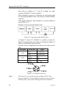
1. The autopilot system detects whether a reversible motor or a
solenoid is connected and outputs the correct drive signal
automatically.
2. The drive output of AC10 is sufficient for any type of 12 and
24V solenoids normally found on a recreational boat.