


Installation
20221586B 59
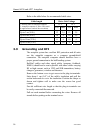
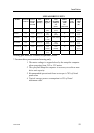
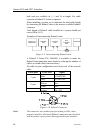
LINEAR DRIVE UNITS
MODEL MOTOR
VOLTS
AUTO-
PILOT
COM-
PUTER
MAX
STROKE
mm (in.)
PEAK
THRUST
kg (lb.)
MAX
RUDDER
TORQUE
Nm
(lb.in.)
HARD-
OVER
TIME
sec.
(30% load)
PWR.
CON-
SUMP.
TILLER
ARM
mm
(in.)
MLD200 12V AC10 300 (11,8) 200
(440)
490
(4350)
15 1,5-6 A 263
(10,4)
HLD350 12V AC10 200 (7,9) 350
(770)
610
(5400)
12 2,5-8 A 175
(6,9)
HLD2000L 12V AC20 340 (13,4) 500
(1100)
1460 (12850) 19 3-10 A 298
(11,7)
HLD2000D 24V AC20 200 (7,9) 1050
(2310)
1800
(15900)
11 3-10 A 175
(6,9)
HLD2000LD 24V AC20 340 (13,4) 1050
(2310)
3180
(28000)
19 3-10 A 298
(11,7)
MSD50* 12V AC10 190 (7,5) 60
(132)
– 15 0,8-2 A –
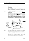
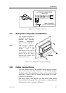
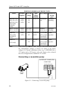
Steering gear interface: Connects to quadrant or tiller.
* For stern drive power assisted steering only.
1. The motor voltage is stepped down by the autopilot computer
when operating from 24V or 32V mains.
2. The specified autopilot computer is necessary to achieve max
drive unit capacity.
3. Recommended operational thrust or torque is 70% of listed
peak value.
4. Typical average power consumption is 40% of listed
maximum value.