


Simrad AP26 and AP27 Autopilots
68 20221586B
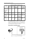
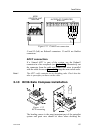
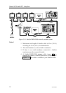
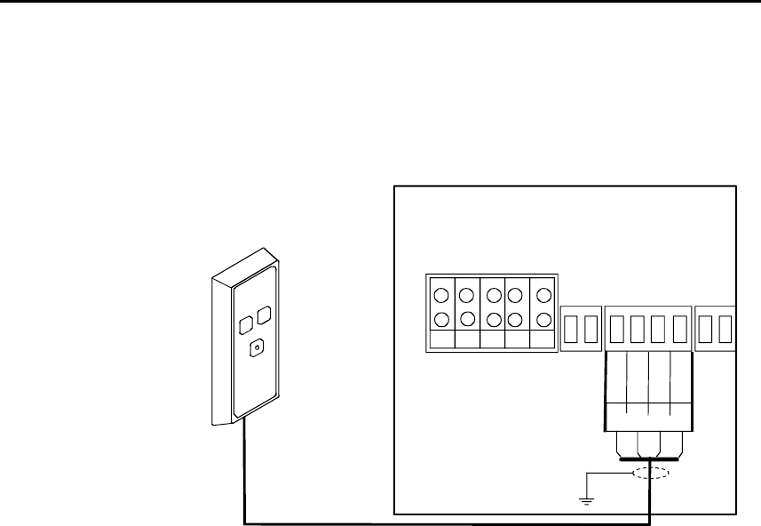
3.15 R3000X Remote Control installation
R3000X should be mounted in the supplied bracket that can be
fixed by four mounting screws. The unit is weather proof and
can be mounted outdoor.
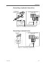
TB6
AUTOPILOT COMPUTER
TB3 TB4
TB5
TB7
Stbd
Port
Gnd
Gn
Red Blu
REMOTE
TB8
TB1
TB2
R3000X
REMOTE CONTROL
Lamp
Yel
POWER PCB
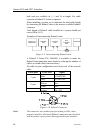
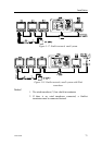
Figure 3-15 R3000X connection
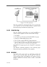
3.16 JS10 Joystick
Refer to separate installation procedure for JS10 Joystick.
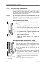
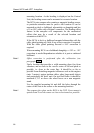
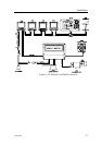
3.17 S35 NFU Lever installation
The unit is mounted to a bulkhead or panel by two screws from
the front. The cable is connected to the autopilot computer
according to Figure 3-16. Interchange the Port and Stbd wires to
the screw terminals if necessary to make the direction of the
lever movement coincide with the direction of the rudder
movement.