


1-8
PCS-1/1P
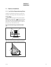
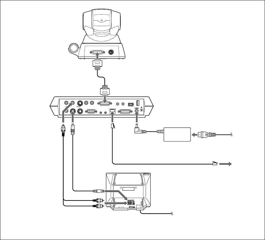
1-3. System Connections
This section describes the typical system connections.
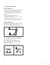
m
. Be sure to turn off all the equipment before making any connections.
. Do not connect/disconnect the camera cable with the power on. Doing so may damage the Camera Unit
or Communication Terminal.
. For safety, do not connect the 100BASE-TX/10BASE-T connector to a network that applies an excess
voltage via the 100BASE-TX/10BASE-T connector
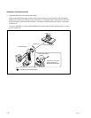
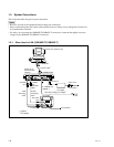
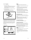
1-3-1. When Used in LAN (100BASE-TX/10BASE-T)
DC 19.5V
AUDIO OUT
AUDIO IN
AUX1–
VIDEO IN
–AUX2
CAMERA UNIT MIC
(PLUG IN POWER)
ISDN UNIT
WHITE
BOARD
(MIXED)
AUX
MAIN
–
MONITOR
–
SUB
VIDEO OUT
RGB OUT DSB
IR OUT
100BASE-TX
10BASE-T
12
12
TERMINAL VISCA OUT
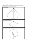
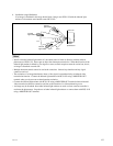
PCS-C1/C1P Camera Unit
to TERMINAL
Camera cable
*
to CAMERA UNIT
to DC19.5 V
Power cord
*
to wall outlet
to 100BASE-TX/
10BASE-T
PCS-AC195
AC adaptor
UTP cable (category 5, straight)
**
TV monitor
**
to a wall outlet
to LAN
to AUDIO
OUT
to VIDEO
OUT
MONITOR
MAIN
S-video
connecting
cable
*
to S-video
input
to audio input
*
supplied
**
not supplied
Audio
connecting
cable
*
PCS-P1/P1P
Communication
Terminal