


3-9
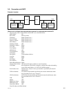
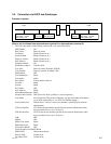
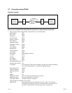
PCS-1/1P
Teleconference terminal A
User name: PCS1A
User number: 100
Teleconference terminal B
User name: PCS1B
User number: 200
DHCP
server A
DHCP
server B
Gatekeeper
192.100.10.20
LAN1 LAN2
Router Router
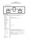
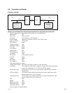
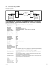
3-5. Connection via DHCP and Gatekeeper
Example of system
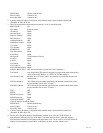
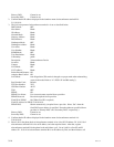
When a call is initiated from teleconference terminal A to teleconference terminal B.
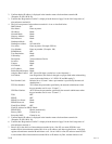
1. The LAN setup menu of teleconference terminal B is set as described below.
DHCP Mode: ON
Host Name: Enter any name.
IP Address: Blank (Cannot be set.)
Network Mask: Blank (Cannot be set.)
Gateway Address: Blank (Cannot be set.)
DNS Address: Blank (Cannot be set.)
Gatekeeper Mode: ON
Gatekeeper Address: 192.100.10.20
User Alias: Enter any name. (Example: PCS1B)
User Number: Enter any number. (Example: 200)
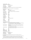
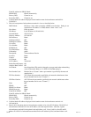
SNMP Mode: OFF
Trap Destination: Blank
Community: public
Description: Videoconference Device
Location: Blank
Contact: Blank
NAT Mode: OFF
NAT Address: Blank
Packet Resend Request: Blank
Adaptive Rate Control: OFF (Set to ON when a packet loss occurs frequently.)
LAN Mode: Auto Nagotiation (This mode is changed to a proper mode when mismatching
occurs in the mode. Refer to “4-2. PCS-1/1P and Hub setting”.)
Port Number Used: Default (Set to “Custom” when a port number is specified by the network
administrator.)
TCP Port Number: 2253 (Enter the port number specified by the network administrator when
the port number used is set to “Custom”.)
UDP Port Number: 49152 (Enter the port number specified by the network administrator when
the port number used is set to “Custom”.)
TOS: OFF
PPPoE: OFF
PPPoE User Name: Blank
PPPoE Password: Blank
Fixed IP for PPPoE: OFF
Fixed IP Address for PPPoE: Blank
PPPoE DNS: Obtain automatically
Primary DNS: Cannot be set.
Secondary DNS: Cannot be set.