


CP180 / CP180i Page 15
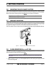
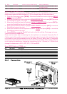
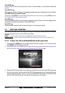
1. Remove the threaded base from the antenna dome.
2. To ease installation a flush mounting template for the antenna has been included.
3. Apply the mounting template sticker to the area that was verified for GPS reception.
4. Then, drill out the 0.63” (16mm) and 0.16” (4mm) holes, and remove the template.
5. Insert the cable into the 0.63” (16mm) hole and route to the GPS chart plotter.
6. Apply a small amount or RTV to the under side of the antenna.
7. Place the antenna and then screw it into place using the screws. In some cases the
screw may not be long enough, if this happens simply apply more RTV to the underside
of the antenna to glue it into place.
Figure 2.3.0 - Installing the GPS WAAS Smart antenna (I)
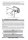
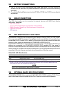
GPS OVERALL SHAPE
CUTTING TEMPLATE
CUTTING TEMPLATE
4 mm [0.155"]
4 mm [0.155"]
0
0
16 mm [0.63"] or greater
0
0
4 mm [0.155"]
Figure 2.3.0a - Installing the GPS WAAS Smart antenna (II)
2.4 CONNECTIONS
The CP180 or CP180i has connectors that are used to connect to the power supply, GPS
antenna (CP180 only) optional FF520 Fish Finder and to NMEA devices such as Marine
VHF radio, digital instruments, autopilots and AIS receivers.
NOTE
The GPS chart plotter can send many sentences to external NMEA devices. The NMEA output wires
are Yellow, Brown and White. If you have connected devices as shown in the below table and need
to feed NMEA to other devices (Autopilot, RADAR…) you can parallel wires from the Yellow, Brown
or White wires.
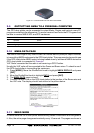
2.4.0 Connection Table
12VDC Power and NMEA Cable
Pin Wire Color Description Connection Example Additional Comments
1 Black Battery Ground Connect to Battery Ground
2 Red Battery Positive Connect to Battery Positive
3 Green NMEA Common Common for NMEA devices
4 Blue Port1 Input Connect to Output of NMEA device Default is NMEA0183
5 Brown Port1 Output Connect to Input of NMEA device Default is NMEA0183 with GLL, RMB, RMC
and XTE sentences